Electrical control for engine

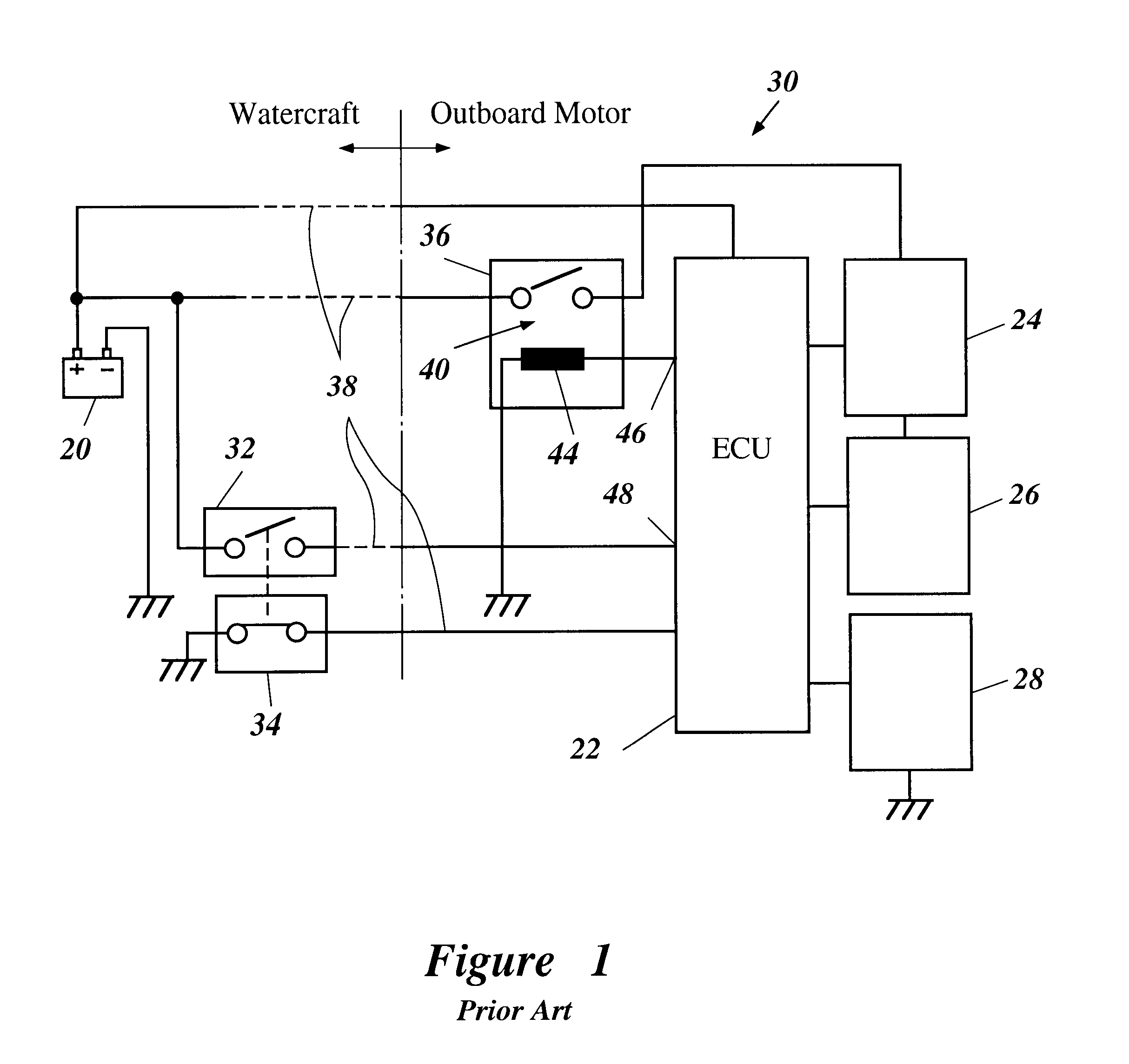
a technology of electric control and engine, applied in the direction of electric control, engine starters, speed sensing governors, etc., can solve the problems of increasing the size and associated cost of ecu 22, affecting engine operation, and increasing the cost of ecu 22

Inactive Publication Date: 2003-07-22
YAMAHA MARINE KK
View PDF22 Cites 32 Cited by
  • Summary
  • Abstract
  • Description
  • Claims
  • Application Information

AI Technical Summary

Benefits of technology

have been described above. Of course, it is to be understood that not necessarily all such objects or advantages may be achieved in accordance with any particular embodiment of the invention. Thus, for example, those skilled in the art will recognize that the invention may be embodied or carried out in a manner that achieves or optimizes one advantage or group of advantages as taught herein without necessarily achieving other objects or advantages as may be taught or suggested herein. Moreover, further aspects, features and advantages of this invention will become apparent from the detailed

Problems solved by technology

Malfunctions with the ECU, therefore, can impair engine operation.
The provision of the seperate control circuit necessarily increases the size and associated cost of the ECU 22.
This increases the cost of the ECU 22 and occasionally requires a larger connector size.

Method used


Image

  • Electrical control for engine
  • Electrical control for engine
  • Electrical control for engine

Examples


Embodiment Construction

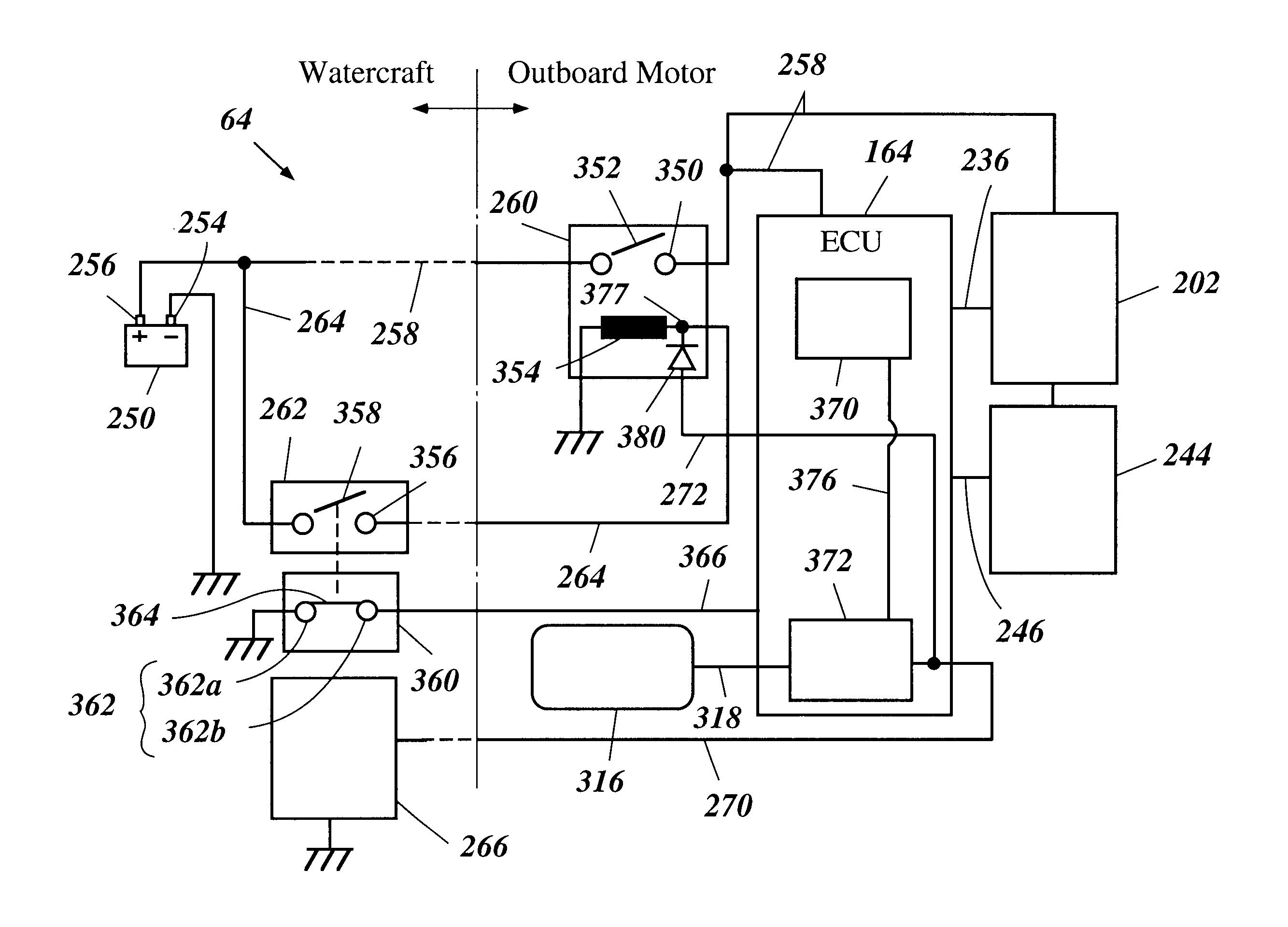
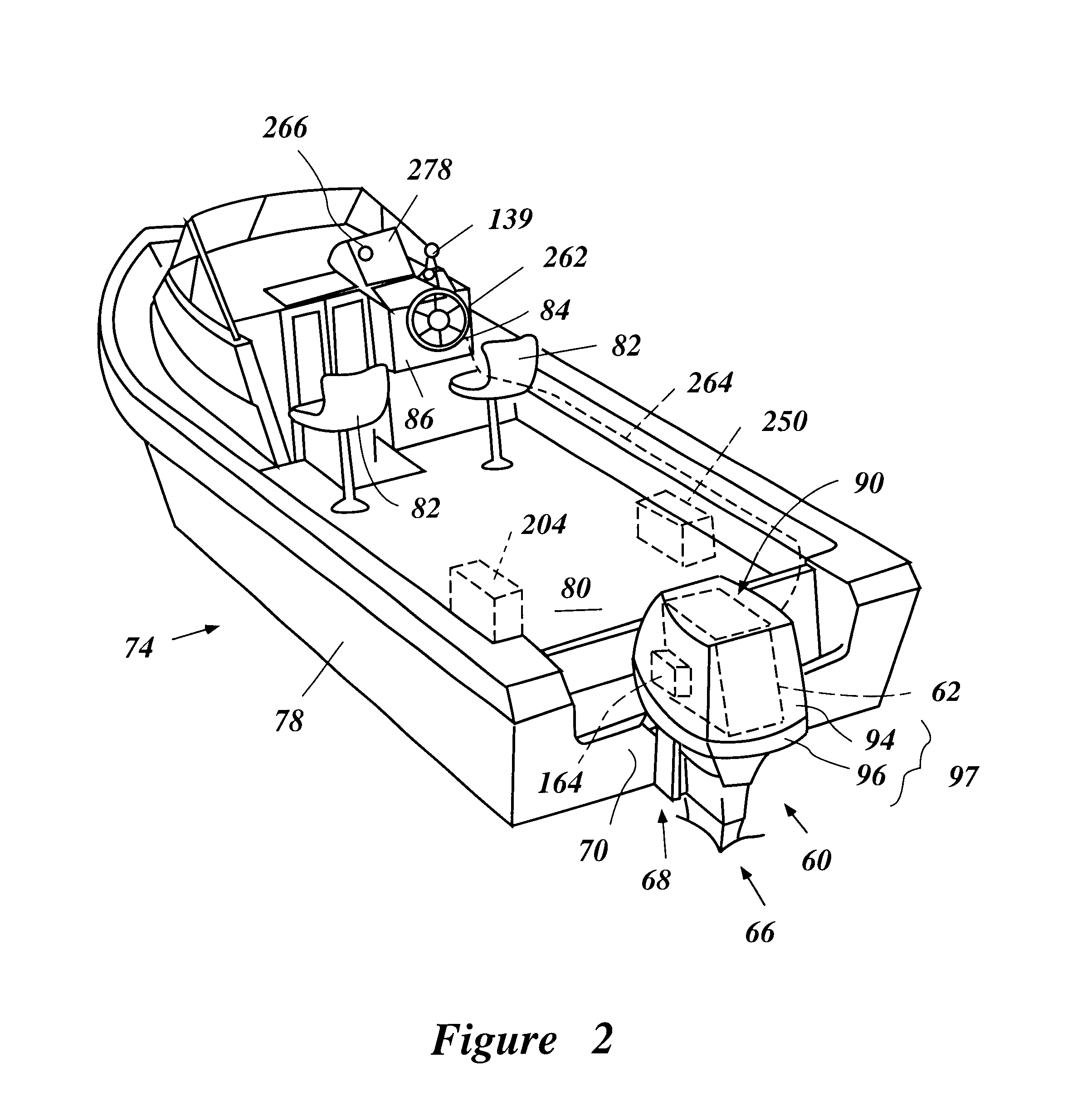
With reference now to FIGS. 2 to 5, an outboard motor, designated generally by the reference numeral 60, includes an internal combustion engine 62 which has a power supply system 64 arranged in accordance with certain features, aspects and advantages of the present invention. Although the present invention is shown in the context of an engine for an outboard motor, various aspects, features and advantages of the present invention also can be employed with other engines such as, for example, watercraft, all terrain vehicles, automobile and motorcycle engines.

In the illustrated embodiment, the outboard motor 60 comprises a drive unit 66 and a bracket assembly 68. Although schematically shown in FIGS. 2 and 3, the bracket assembly 68 actually comprises a swivel bracket and a clamping bracket. The swivel bracket supports the drive unit 66 for pivotal movement about a generally vertically extending steering axis. The clamping bracket, in turn, is affixed to a transom 70 of an associated ...


PUM


Abstract

An electrical control system for an engine includes a power supply system that supplies electric power to an engine control unit. The system has a power source connected to the engine control unit via a locking relay. The relay includes an exciting coil that is energized by electrical power when a main switch is closed. The control unit comprises a tacho-pulse shaping circuit or a fuel pump drive circuit that outputs a signal that prolongs the energized state of the coil after the main switch is opened. The signal prolongs the energized state of the coil for a preset time.

Description

PRIORITY INFORMATIONThis application is based on and claims priority to Japanese Patent Application No. 11-046,618, filed Feb. 24, 1998, the entire contents of which is hereby expressly incorporated by reference.1. Field of the InventionThe present invention generally relates to an electrical system for an engine. More particularly, the present invention relates to an improved electrical system that comprises a control unit and a power supply circuit that is connected to the control unit through a time delay switch.2. Description of Related ArtRecently, engine designers have been emphasizing decreasing emissions, improving fuel economy and, at the same time, maintaining if not improving power output. One way of obtaining at least some of these results involves electrically controlling any of a variety of engine operations. For instance, ignition timing can be altered to better reflect changing engine operating parameters. Moreover, certain characteristics of fuel injected engines ca...

Claims


Application Information

Patent Timeline
Patent Type & Authority Patents(United States)
IPC IPC(8): F02D37/00F02D41/14F02D37/02F02D31/00F02B61/00F02B61/04F02N11/04F02D45/00F02D41/22
CPCF02B61/045F02D31/008F02D35/027F02D37/02F02D41/1481F02D2041/389F02D2200/0404F02D2200/0406F02D2200/0414F02N11/04
Inventor KANNO, ISAO
Owner YAMAHA MARINE KK
Why Eureka
Try Eureka