Surface light emitting device

a light emitting device and surface technology, applied in the direction of instruments, lighting and heating apparatus, planar/plate-like light guides, etc., can solve the problems of insufficient illumination and extremely high luminan

Inactive Publication Date: 2003-08-05
NICHIA CORP
View PDF13 Cites 136 Cited by
  • Summary
  • Abstract
  • Description
  • Claims
  • Application Information

AI Technical Summary

Problems solved by technology

However, in the surface light emitting device of the prior art shown in FIG. 19, there has been such a problem that luminance becomes extremely high in the vicinity of the notch 911 in the first principal plane of the light guide plate.
Also in the surface light emitting device of the prior art shown in FIG. 19, although optical output is made uniform to some extent by the notch 911, it has not been sufficient.

Method used


Image

  • Surface light emitting device
  • Surface light emitting device
  • Surface light emitting device

Examples


embodiment 1

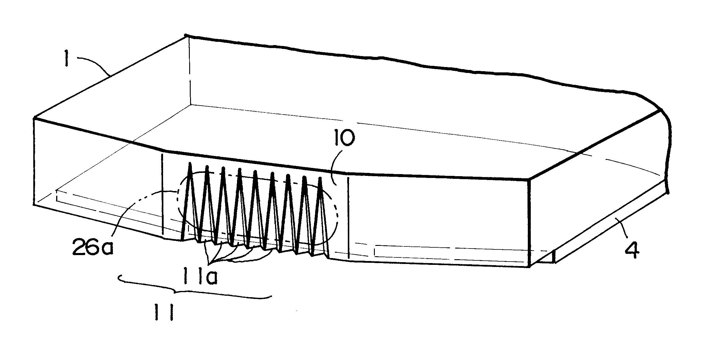
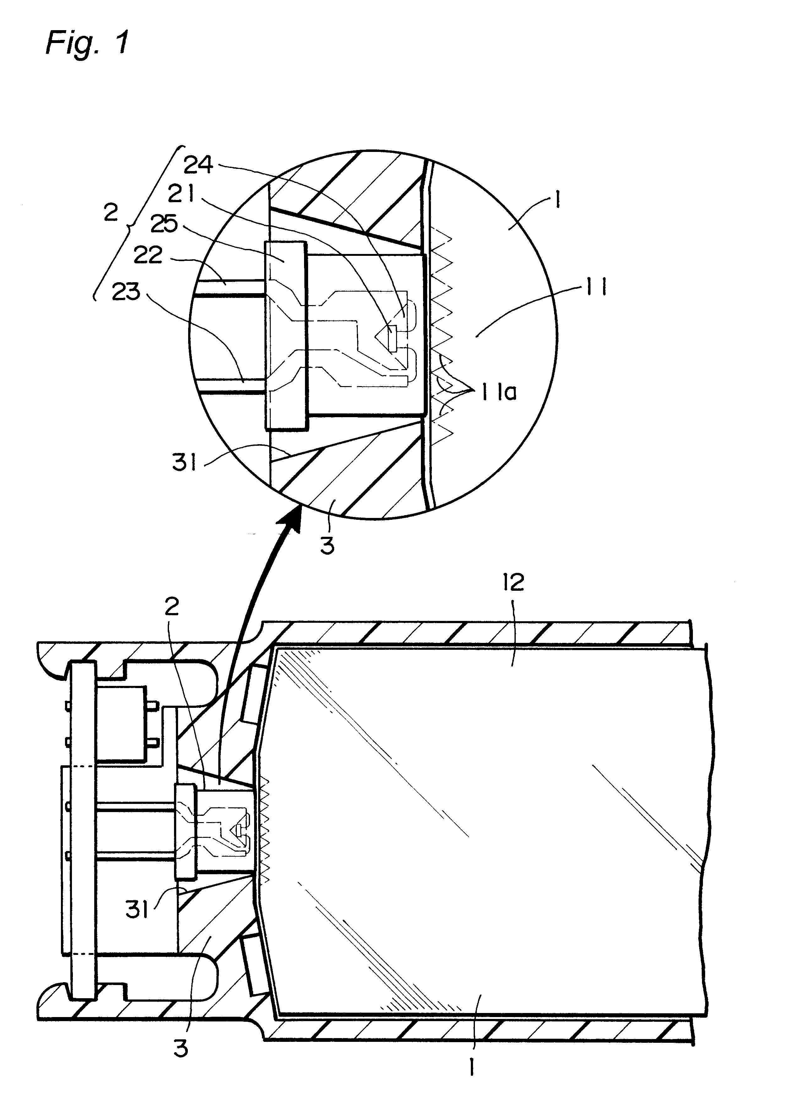
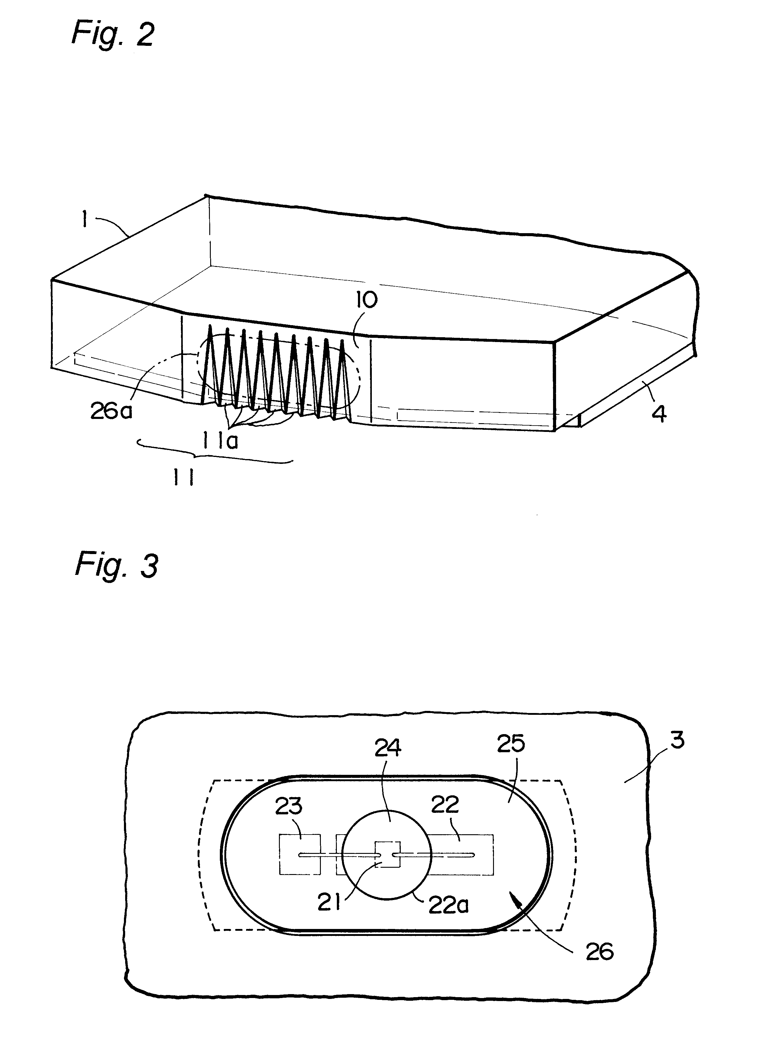
The surface light emitting device according to the first embodiment of the present invention comprises a light guide plate 1 having a reflector 4 provided on the under surface, that is one of opposing principal planes, and the other principal plane serving as a light emitting surface 12, an LED light source 2 having a light emerging surface disposed to oppose an incidence surface that is one end face of the light guide plate 1, and a support 3 that is made of a molded resin and holds the light guide plate 1 and the LED light source 2 in a predetermined positional relationship.

The surface light emitting device according to the first embodiment is particularly characterized in that a light diffusing portion 11 having a plurality of notches of triangular cone shape 11a is formed at such a position that opposes a light emerging surface 26 of the LED light source 2 in the light input end face of the light guide plate 1. This configuration makes it possible to suppress the abnormal light ...

embodiment 2

Now a surface light emitting device of the second embodiment of the present invention will be described below.

The surface light emitting device of the second embodiment comprises an LED bar light source 100 and a light guide plate 101 as shown in FIG. 4.

In the second embodiment, the LED bar light source 100 has a plurality of light emitting portions 102 as shown in FIG. 4 and FIG. 5, and the light emitting portions 102 are made by mounting LED chips 21 in recesses 131 formed on a side face of a bar body 125 made of a resin for injection molding, and filling the recesses with a light transmitting resin 124.

The light transmitting resin 124 include a phosphor that absorbs light emitted by the LED chip 21 and emits light of a wavelength different from that of the light absorbed, so that light of desired color is emitted from the light emerging surface 126 by mixing the light emitted by the LED chip 21 and light emitted by the fluorescent substance.

In the surface light emitting device of...

modification 1

A surface light emitting device of the first modification of the present invention is made in the same constitution as the surface light emitting device of the second embodiment except for the light guide plate 101 where the light diffusing portion is constituted from one notch 105 of triangular pyramid shape instead of the plurality of notches 111a.

The notch 105 of triangular pyramid shape in the surface light emitting device of the first modification is formed to be larger than the notches 11a, 111a of the first and second embodiments.

In the surface light emitting device of the first modification, the notch 105 is made in a shape of triangular pyramid that expands from an apex located at a point spaced from the light emitting surface on the end face of the light guide plate 101 downward to the under surface where the reflecting surface 4 is formed.

In the surface light emitting device of the first modification made in the constitution described above, since the notch 105 has two su...


PUM

PropertyMeasurementUnit
temperatureaaaaaaaaaa
injection pressureaaaaaaaaaa

Abstract

An surface light emitting device that is capable of emitting light of high luminance with higher uniformity is disclosed.The surface light emitting device comprising; a light guide plate, a reflector on the under surface of the light guide plate and, an LED light source having at least one LED element and provided so that a light emitted by the LED element is incident on at least one end face of the light guide plate, wherein the light guide plate has a light diffusing portion on the one end face so that a light emitted from the LED light source enters the light guide plate while being diffused therein, and the light diffusing portion has the top end being space from the top surface.

Description

The present invention relates to a surface light emitting device that is capable of emitting light, received from LED chips that are point light sources, uniformly over a light emitting surface of a light guide plate and is used for the back light of a liquid crystal display, panel meter, indicator light and surface light emitting switch.DESCRIPTION OF THE RELATED ARTRecently surface light emitting device, that effects surface emission of light by receiving light from LED chips which are point light sources, has been used as light sources such as the back light of liquid crystal display. The surface light emitting device is made in such a configuration that light, which is emitted by one or more light emitting diodes and is incident on one end face of a light guide plate that has opposing principal planes, is caused to emerge from the entire surface of one of the principal planes of the light guide plate. In the surface light emitting device, it is important to extract uniform optic...

Claims


Application Information

Patent Timeline
Patent Type & Authority Patents(United States)
IPC IPC(8): F21V8/00G02B6/00F21Y101/02G02F1/1335G02F1/13357H01L33/50H01L33/60
CPCG02B6/0016G02B6/002
Inventor EHARA, MUNETSUGUNOJIRI, HITOSHINAKANISHI, EIJIKUNIKATA, KOICHI
Owner NICHIA CORP
Why Eureka
Try Eureka