Method for treating waste gas containing fluorochemical

a waste gas and fluorochemical technology, applied in the direction of physical/chemical process catalysts, separation of dispersed particles, separation processes, etc., can solve the problems of low decomposition rate, short life of the treating agent, and no method using it has been found effectiv

Inactive Publication Date: 2003-08-05
EBARA CORP
View PDF13 Cites 25 Cited by
  • Summary
  • Abstract
  • Description
  • Claims
  • Application Information

AI Technical Summary

Problems solved by technology

In the semiconductor industry, many kinds of hazardous gases are used in the semiconductor manufacturing process, arousing concern for environmental contamination by them. C.sub.2 F.sub.6, contained in an exhaust gas from a chemical vapor deposition (CVD) step and an etching step, acts as a global warming gas, and the establishment of a system for its removal is considered to be an urgent task.
However, none of methods using them have been found effective.
However, all of the methods of this type have involved drawbacks, such as a low decomposition rate, a short life of the treating agent, and occurrence of carbon monoxide (CO) as a by-product which is difficult to treat.

Method used


Image

  • Method for treating waste gas containing fluorochemical
  • Method for treating waste gas containing fluorochemical
  • Method for treating waste gas containing fluorochemical

Examples


examples

The present invention will now be described concretely by way of Examples, but the invention is not restricted thereby.

reference examples 1 to 4

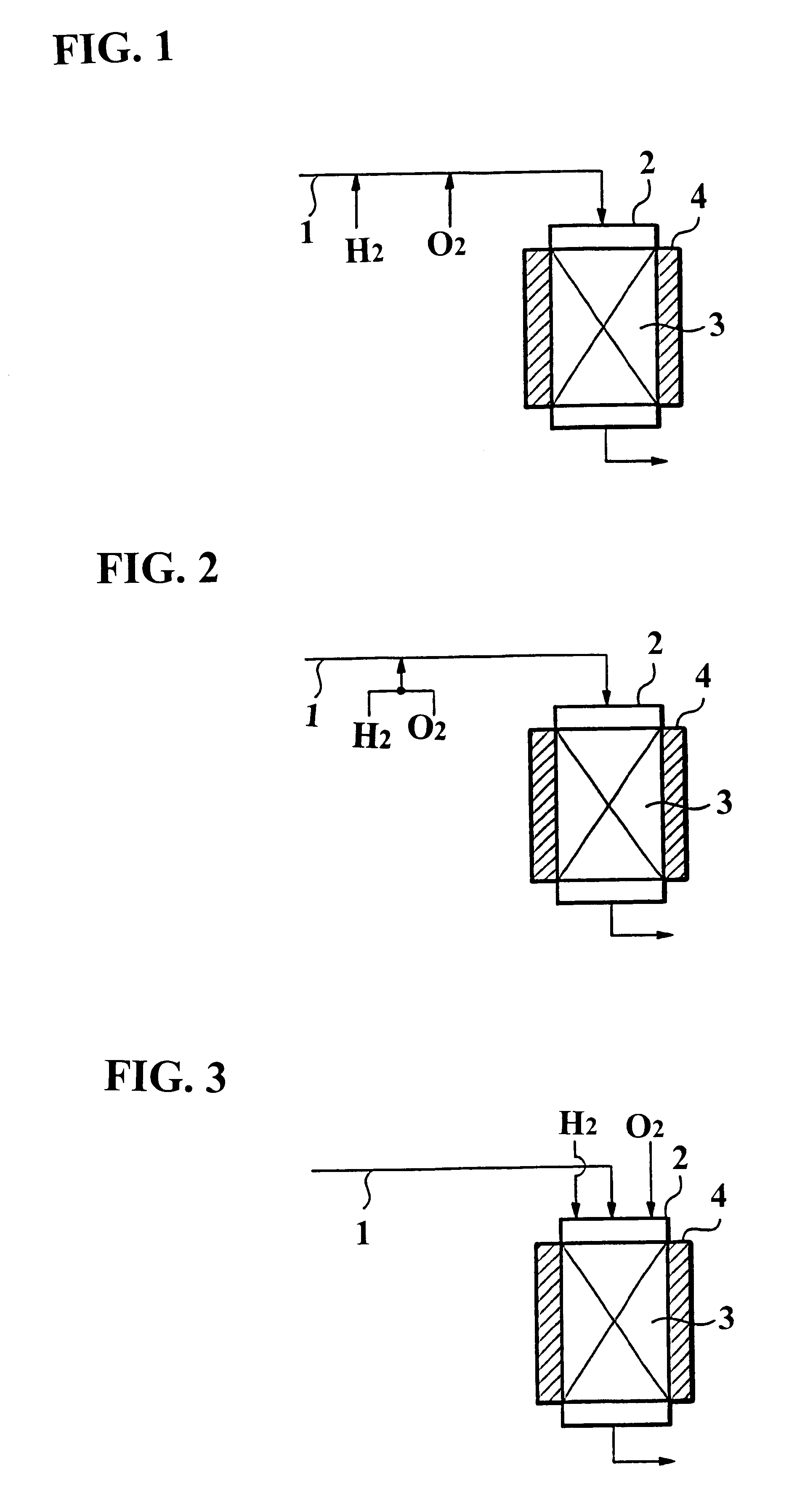
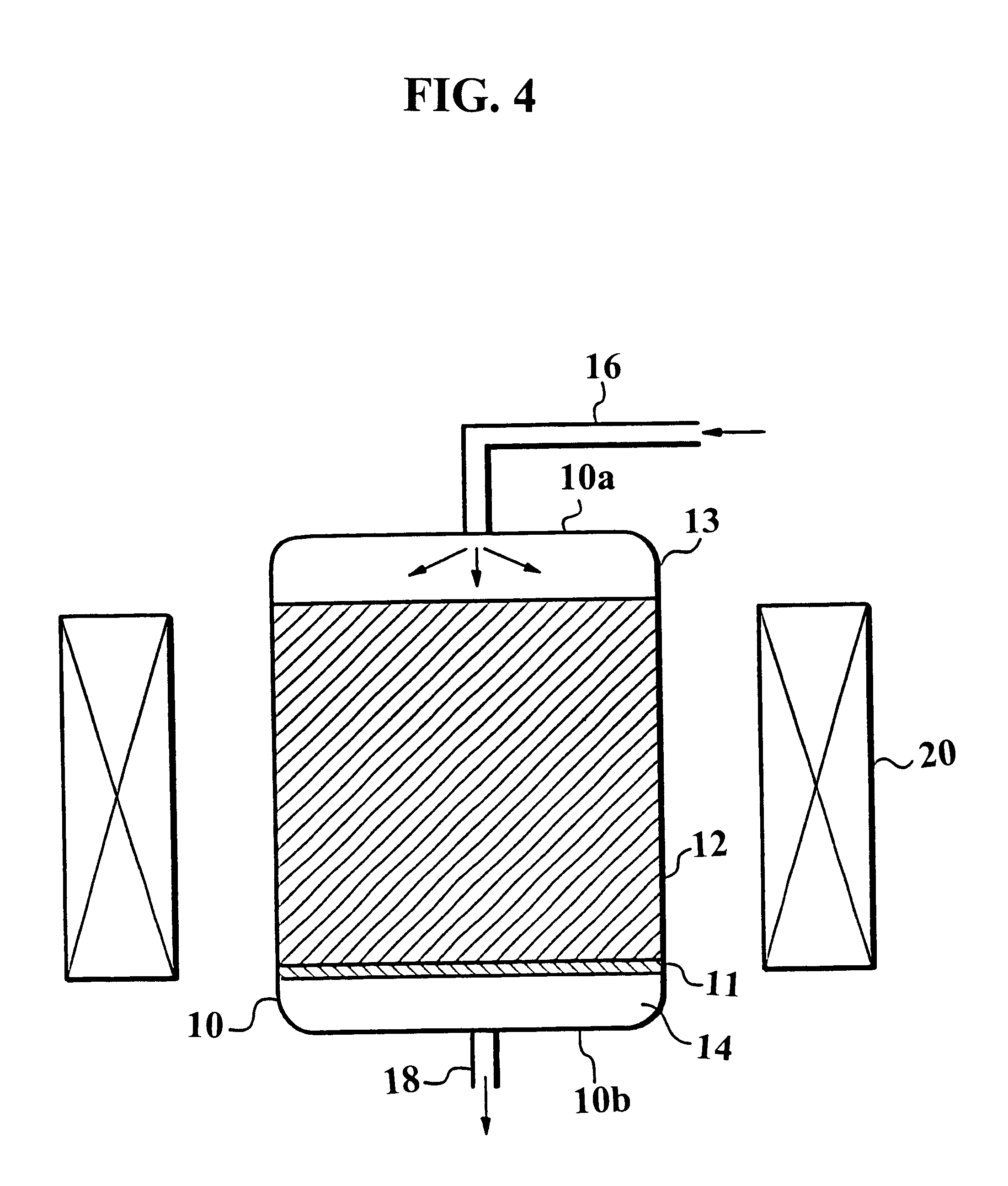
A quartz column with a diameter of 25 mm was used, and packed with a treating agent to a layer height of 100 mm.

The packed column was mounted in a ceramic electric tubular furnace, and the treating agent layer was heated to 700.degree. C. A gas of C.sub.2 F.sub.6 alone diluted with an N.sub.2 gas was passed through the treating agent layer. The flow rate of the gas was 408 sccm, and the SV was set at 500 hr.sup.-1. The inlet gas concentration of C.sub.2 F.sub.6 was adjusted to 1%.

To investigate the treating performance, the outlet gas was analyzed, where necessary. When the removal rate of C.sub.2 F.sub.6 lowered to 90% or less, passage of the gas was stopped, and the amount of C.sub.2 F.sub.6 treated was determined based on the amount of the gas passed by then. The analysis of C.sub.2 F.sub.6 was made using a gas chromatograph equipped with a TCD detector.

The treating agents used were all commercially available products of Mizusawa Kagaku. The treating agents were .gamma.-alumina (...

example 8

Test for treatment of CF.sub.4 was conducted using Neobead GB-08 (a product of Mizusawa Kagaku, principal component: .gamma.-alumina) as .gamma.-alumina.

The same testing equipment as in Example 1 was used, and CF.sub.4, H.sub.2 and O.sub.2 gases were passed under the conditions described below. The outlet gas was analyzed where necessary, to investigate the treating performance of CF.sub.4. The experimental conditions are shown below.

A nitrogen gas containing CF.sub.4, H.sub.2 and O.sub.2 of the concentrations shown below was continuously passed for 1 to 2 hours. Then, a nitrogen gas containing H.sub.2 and O.sub.2 of the concentrations shown below was introduced for about 1 hour to discharge F remaining in the treating agent as HF. Then, a nitrogen gas containing CF.sub.4, H.sub.2 and O.sub.2 of the concentrations shown below was continuously passed again for 1 to 2 hours. This cycle was repeated.

1 Inflow concentrations:

The amount of H.sub.2 introduced was equivalent (2%) to the amo...


PUM

PropertyMeasurementUnit
temperatureaaaaaaaaaa
particle sizeaaaaaaaaaa
specific surface areaaaaaaaaaaa

Abstract

A method for decomposing a fluorine-containing compound by contacting an exhaust gas 1 containing a fluorine-containing compound, such as C2F6, with aluminum oxide 3, such as gamma-alumina, which has been heated to a high temperature of, for example, 800° C. to 900° C. There may be such a necessary or larger number of moles of H2 that the fluorine atoms in the fluorine-containing compound become HF. The method has a high decomposition rate of a fluorine-containing compound, a long life, and involves minimal occurrence of CO.

Description

The present invention relates to a method and an apparatus for treating an exhaust gas containing a fluorine-containing compound. More particularly, the invention relates to a treatment method and a treatment apparatus for efficiently decomposing C.sub.2 F.sub.6, C.sub.3 F.sub.8, CF.sub.4, CHF.sub.3, SF.sub.6 or NF.sub.3 which is discharged in the step of dry cleaning the internal surface, etc. of a chamber or the like of semiconductor manufacturing equipment with the use of C.sub.2 F.sub.6, C.sub.3 F.sub.8, CF.sub.4, CHF.sub.3, SF.sub.6 or NF.sub.3 in the semiconductor industry, or during etching of various films on a semiconductor device.PRIOR ARTIn the semiconductor industry, many kinds of hazardous gases are used in the semiconductor manufacturing process, arousing concern for environmental contamination by them. C.sub.2 F.sub.6, contained in an exhaust gas from a chemical vapor deposition (CVD) step and an etching step, acts as a global warming gas, and the establishment of a s...

Claims


Application Information

Patent Timeline
Patent Type & Authority Patents(United States)
IPC IPC(8): B01J21/00B01D53/86B01J21/04
CPCB01D53/8659B01J21/04Y02C20/30B01D53/68
Inventor MORI, YOICHI
Owner EBARA CORP
Why Eureka
Try Eureka