Method for correcting downhole NMR data contaminated by borehole signals

a technology of nmr data and signal, applied in the field of detecting borehole contamination and correcting nmr data, can solve the problems of no similar method designed for use in nmr well logging, no device used for the purpose of nmr measurement, and significant amount of washou

a technology of nmr data and signal, applied in the field of detecting borehole contamination and correcting nmr data, can solve the problems of no similar method designed for use in nmr well logging, no device used for the purpose of nmr measurement, and significant amount of washou

US6603310B2Inactive Publication Date: 2003-08-05BAKER HUGHES HLDG LLC

Image

  • Method for correcting downhole NMR data contaminated by borehole signals
  • Method for correcting downhole NMR data contaminated by borehole signals
  • Method for correcting downhole NMR data contaminated by borehole signals

Examples


Embodiment Construction

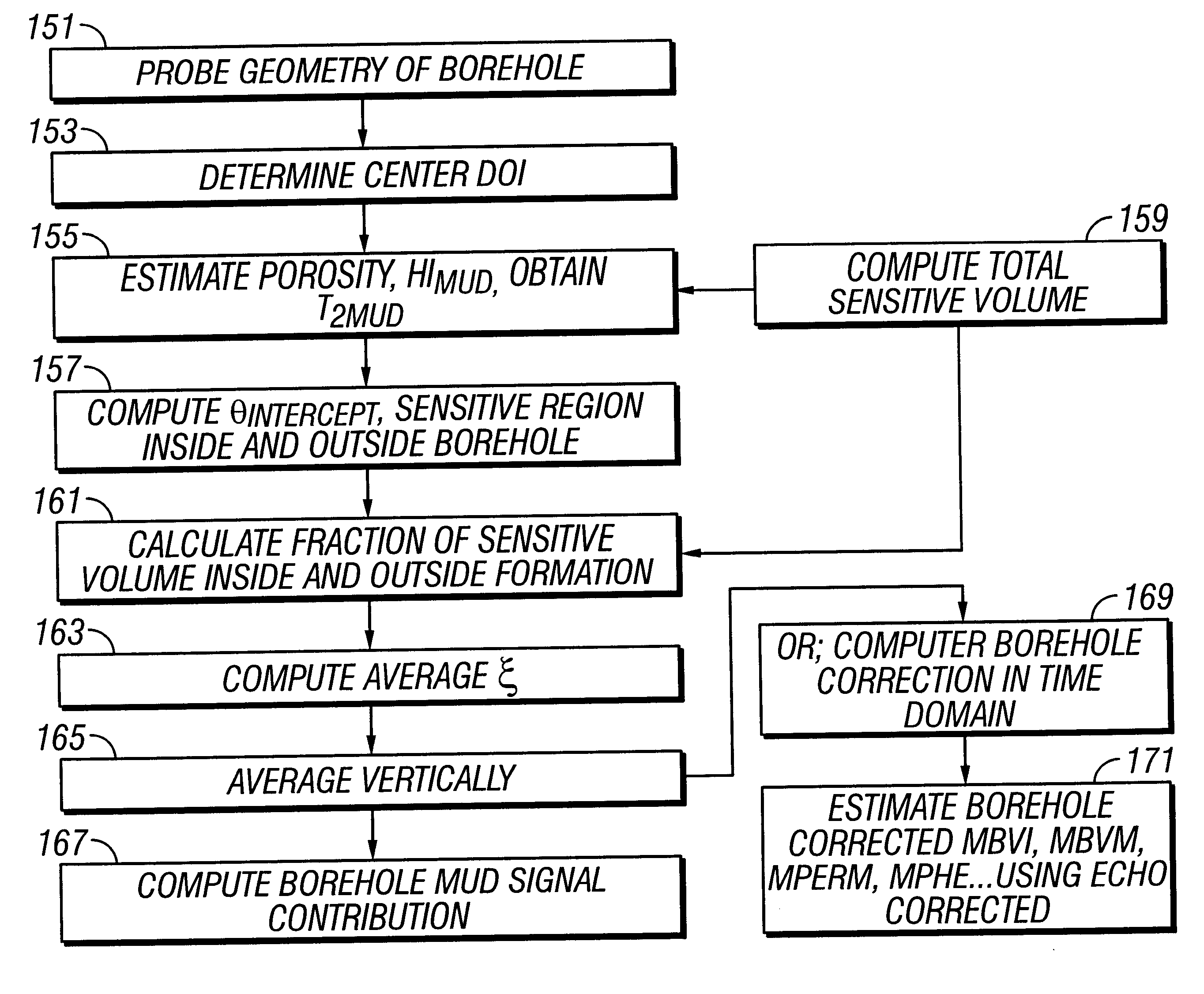
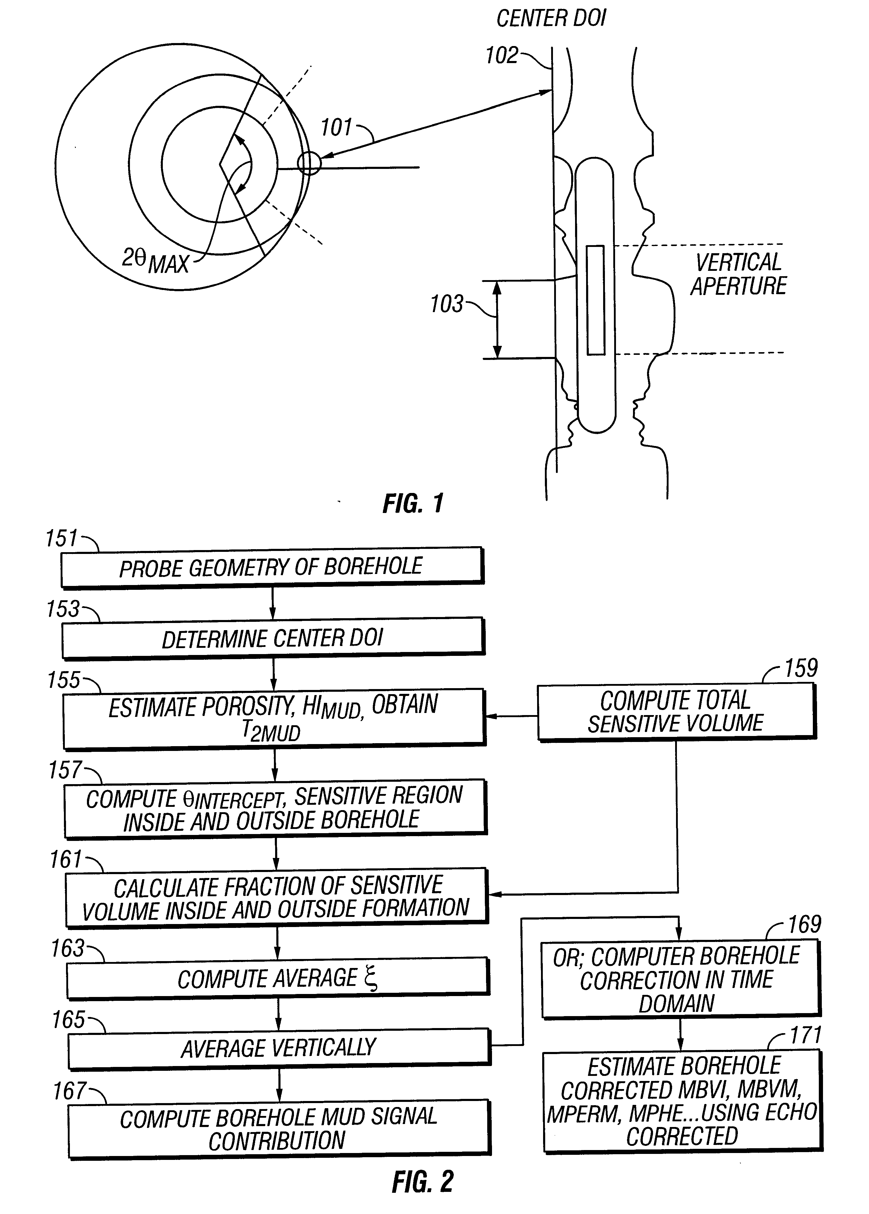
The method of the present invention may be used with any one of several devices. In a preferred embodiment of the invention suitable for use for wireline logging, centralized tool is used, although the method of the present invention is applicable to other tools such as pad devices or side-looking devices. For measurement-while-drilling (MWD) applications, a suitable device is disclosed in U.S. Pat. No. 6,215,304. Such devices are for exemplary purposes only. As would be known to those versed in the art, these NMR tools have a magnet for generating a static magnetic field in the formation and an RF antenna assembly is used to generate a pulsed RF magnetic field in a region of investigation. NMR signals are detected using a receiver antenna and further analyzed to provide information about formation properties such as total porosity, clay bound water, capillary bound water and hydrocarbons.

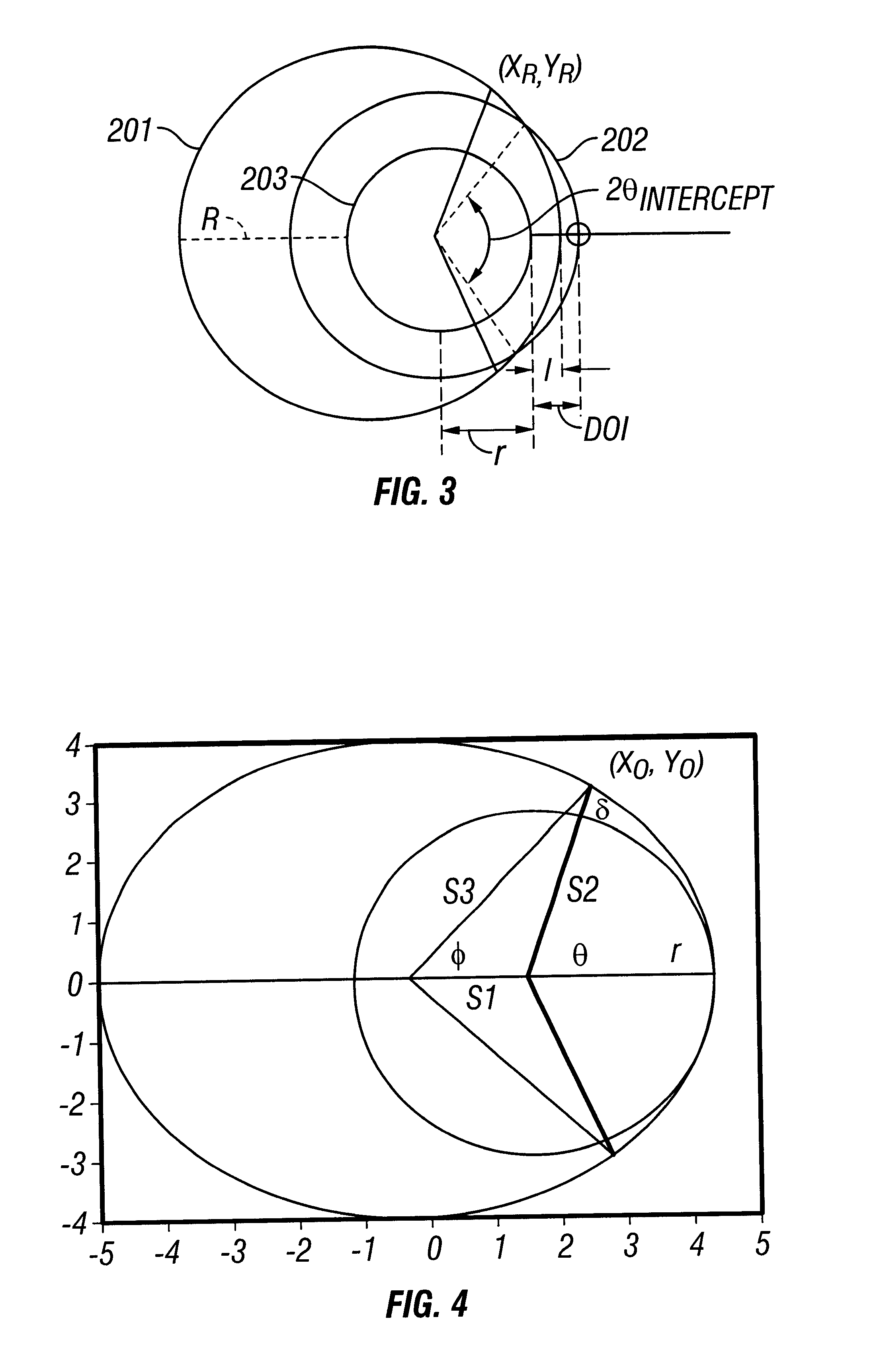
Ideally, in well logging, the sensitive volume of the NMR tool will lie entirely within the roc...


PUM


Abstract

NMR measurements made in a borehole are susceptible to contamination by signals from the borehole fluid. Correction is made for this contamination by using a standoff measuring device to determine the fractional volume of the region of investigation of the NMR tool that lies within the borehole. Using known or determined characteristics of the borehole fluid, a correction is made either to the NMR signals prior to processing or to the processed results of the uncorrected signals.

Description

1. Field of the InventionThe invention is in the field of Nuclear Magnetic Resonance ("NMR") tools and data processing methods. More specifically, the invention pertains to detecting borehole contamination and correcting NMR data for the effects of the contamination in well logging.2. Description of the Related ArtNuclear Magnetic Resonance has uses in many areas, including the fields of medicine, chemistry, non-destructive testing, and in well logging in the oil exploration industry. In the well logging industry, NMR is used in determining properties such as porosity of the formation, permeability, the bound liquid volume, the clay bound volume (CBW) and bulk volume irreducible (BVI), as well as other formation and reservoir fluid properties.In a typical NMR device used in logging, a permanent magnet produces the static magnetic field and establishes the direction of orientation for the nuclear magnetic moments in the vicinity of the borehole. An RF field is applied in the plane pe...

Claims


Application Information

Patent Timeline
05 Aug 2003
Publication
US6603310B2
IPC
G01V3/32; G01V3/18
CPC
G01V3/32
Inventors
GEORGI, DAN T.; CHEN, SONGHUA