

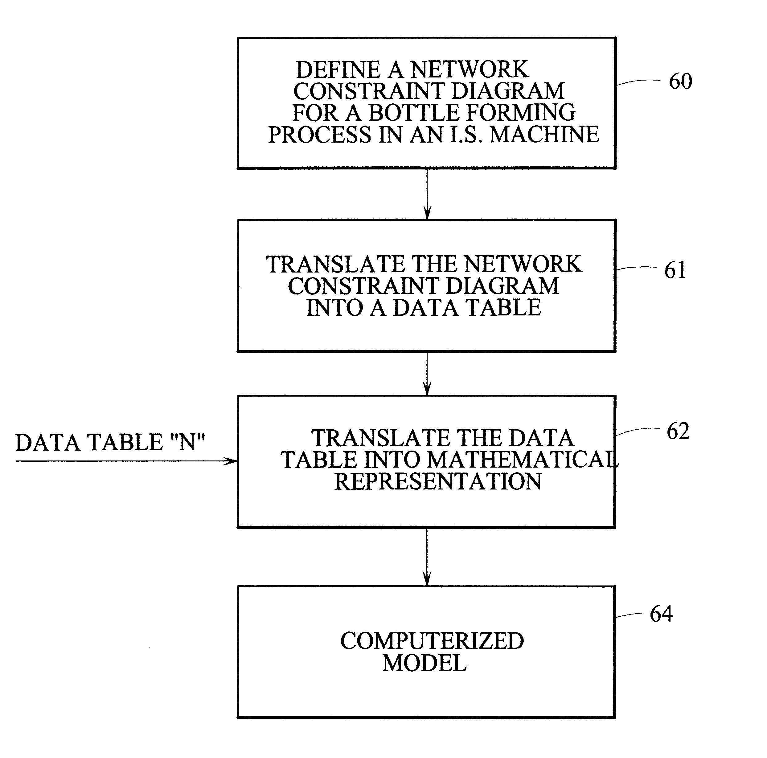
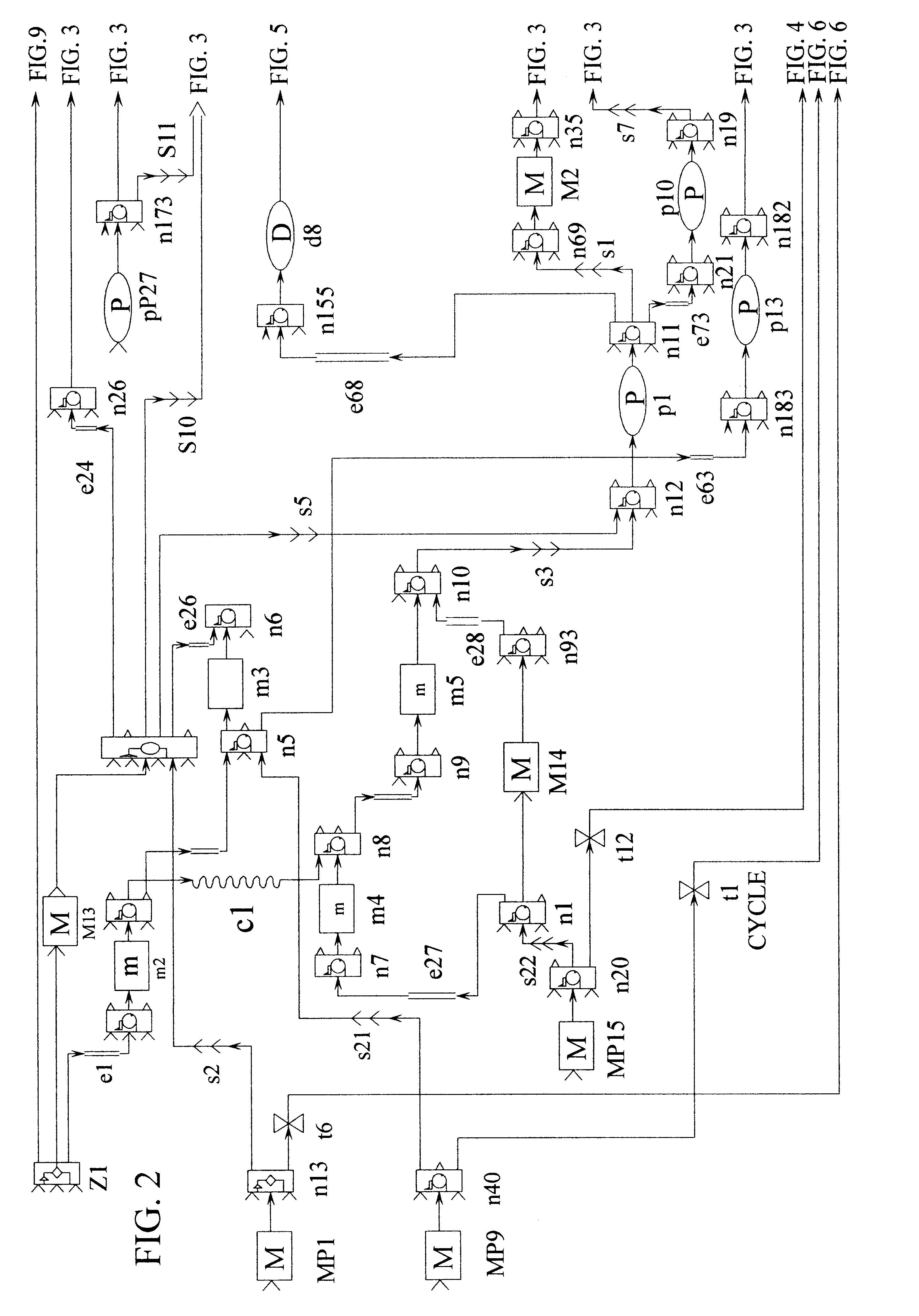
Control for an I.S. machine
a control system and glass forming technology, applied in the direction of programme control, glass blowing apparatus, glass shaping apparatus, etc., can solve the problems of not allowing an operator to directly command the machine, not preventing the user from setting invalid or even potentially damaging sequences, etc., to achieve the effect of minimizing the wear of the displaceable mechanism
- Summary
- Abstract
- Description
- Claims
- Application Information
AI Technical Summary
Benefits of technology
Problems solved by technology
Method used
Image

Examples
Embodiment Construction
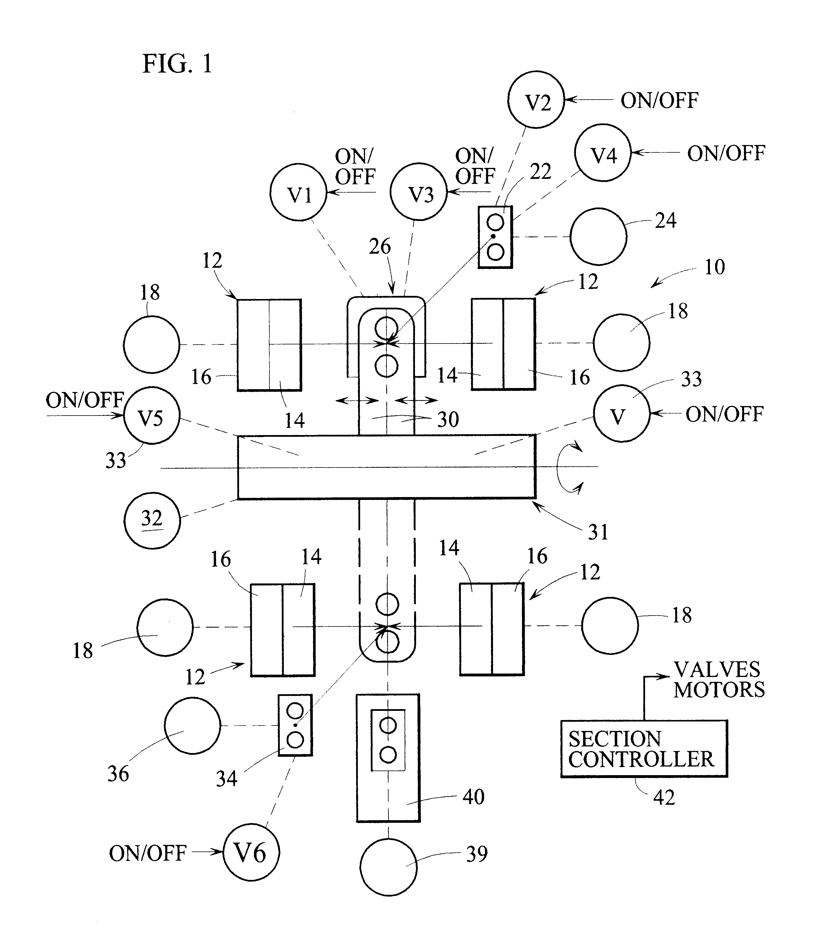
An I.S. machine includes a plurality (usually 6, 8, 10, or 12) of sections 10. Each section has a blank station including a mold opening and closing mechanism 12 having opposed mold supports 14 which carry blank mold halves. When these mold supports are closed by a suitable displacement mechanism 16 which can displace the mold support between open (illustrated) and closed positions and which is displaced by a motor 18 such as a servo motor, discrete gobs of molten glass can be delivered to the closed blank mold. The open top of the blank mold will then be closed by a baffle of a baffle support 22 which is displaceable between remote and advanced positions by a motor (such as a servo) 24. If the section is operating in the press and blow mode, the plunger of a plunger mechanism 26 is advanced vertically upwardly into the gob to form the parison. Cooling air will be supplied to the plunger via a valve V1. If the section is operating in the blow and blow mode, the finish is formed by a...
PUM
| Property | Measurement | Unit |
|---|---|---|
| angles | aaaaa | aaaaa |
| event angle | aaaaa | aaaaa |
| Machine Cycle Event Angles | aaaaa | aaaaa |
Abstract
Description
Claims
Application Information