Window latch system

a window or door latch and sliding technology, applied in the field of sliding latches, can solve the problems of not being able to lock the window or door in an intermediate position, and the interference of the locking mechanism

Inactive Publication Date: 2003-08-19
ELLIOTT GORDON W
View PDF23 Cites 91 Cited by
  • Summary
  • Abstract
  • Description
  • Claims
  • Application Information

AI Technical Summary

Benefits of technology

The present invention includes a combination of simple mechanisms for providing locking and retention of windows or doors within their sliding frame members. The invention allows for integration of a complete latching system into new window or door systems and adaptation to existing installations. Existing installations may be limited in some cases to only allow certain features of the invention to be applied. Diametrically opposing latches are utilized to provide latching points on each side of the window or door. The latches are operated from a common center point hub, enabling the latching and lifting or sliding to be accomplished from this vantage point. The invention allows for the latching system to operate in different modes by means of a selector knob constituting a major advantage to the present invention. Without the innovation of retained selection modes, it would not be possible to lock a window or door in an intermediate position. In addition, the capability of intermediate locking positions supports the innovation of a higher level of building security while doors or windows remain partially open.

Problems solved by technology

The mechanism for locking the window is at the top most frame member, away from the opening, creating interference for defeating the locking mechanism through a partial opening.
Without the innovation of retained selection modes, it would not be possible to lock a window or door in an intermediate position.

Method used


Image

  • Window latch system
  • Window latch system
  • Window latch system

Examples


first embodiment

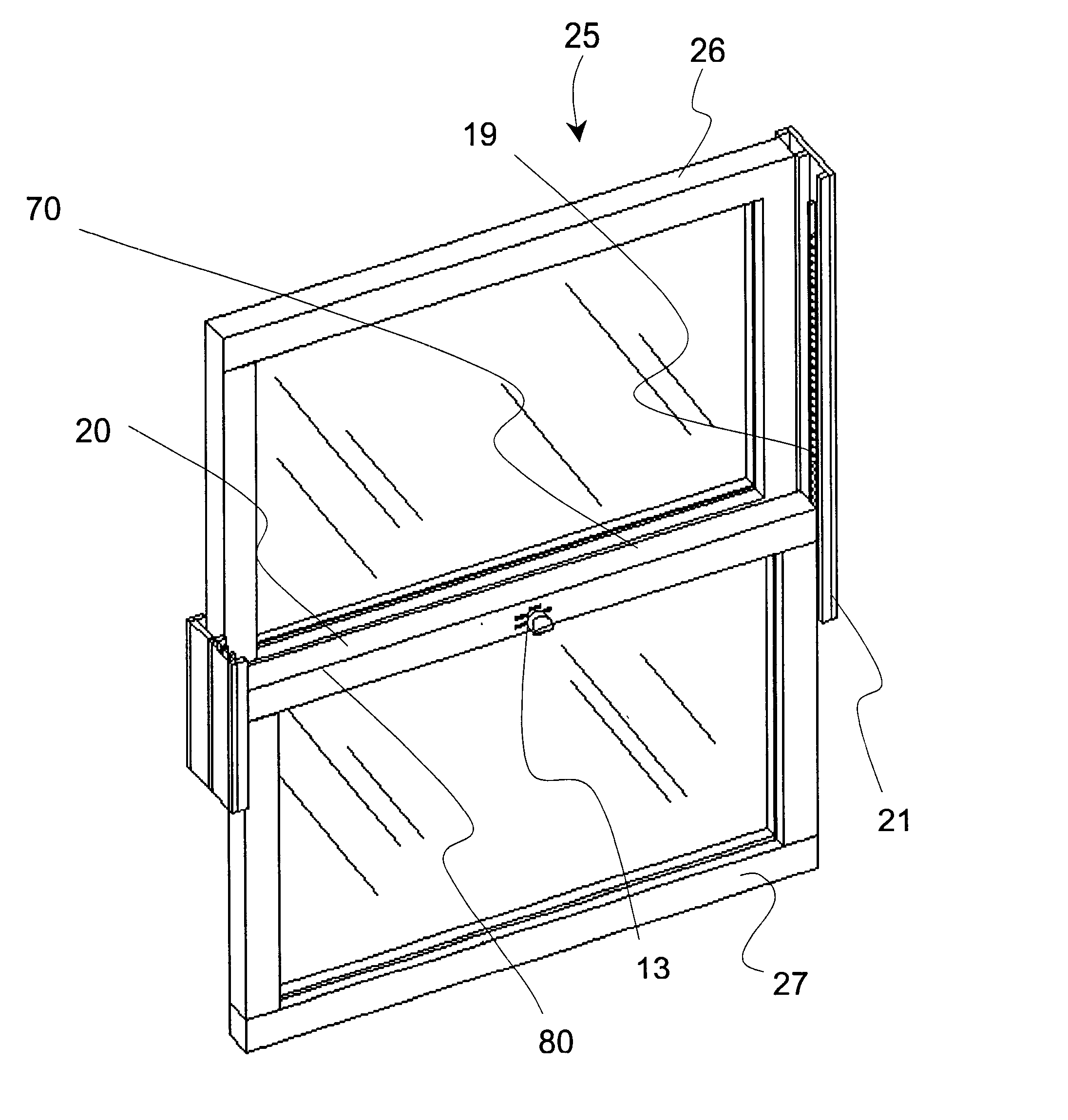
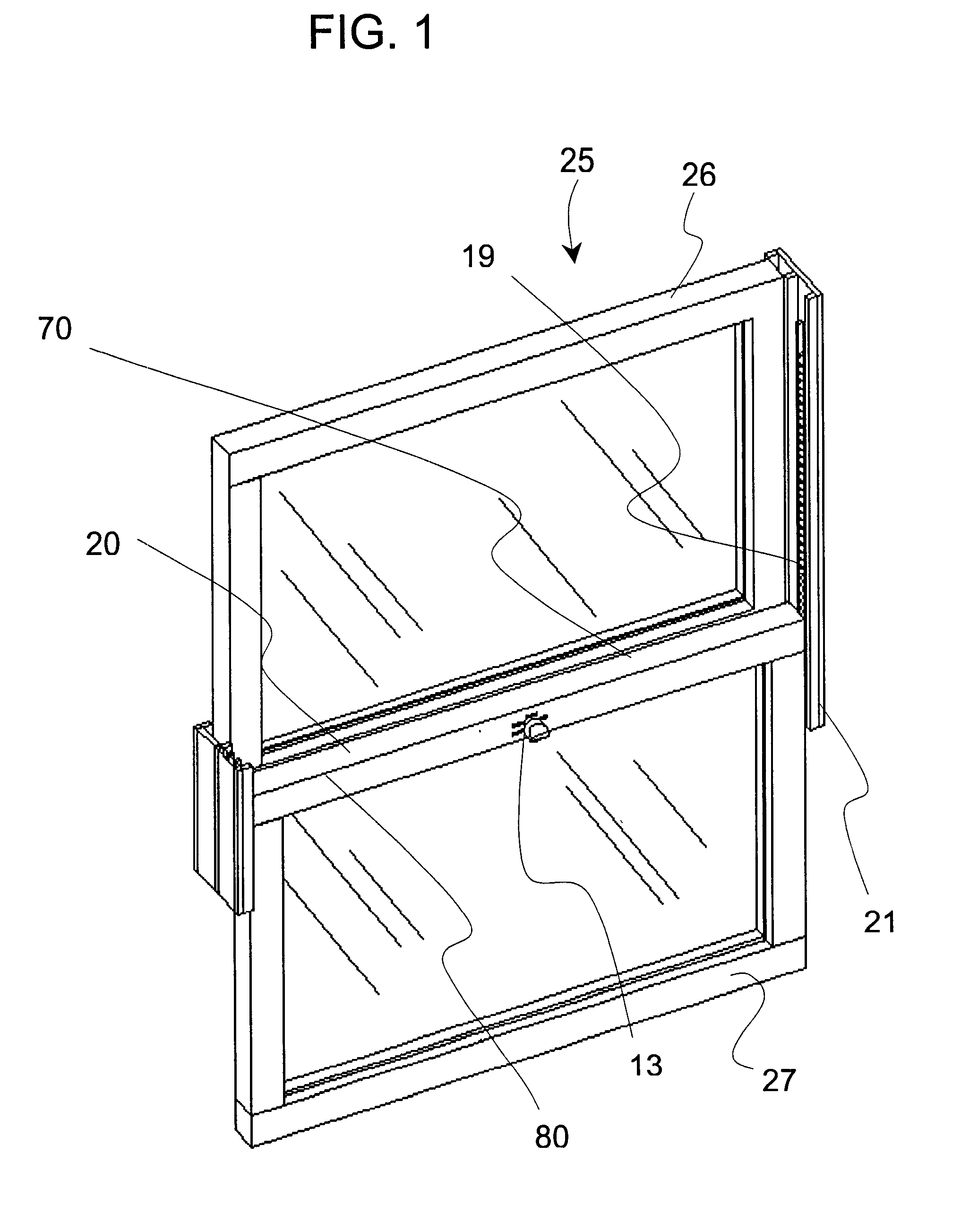
FIG. 1 shows a window employing the window latch system of the present invention. The window 25 has an upper sash 26 and a lower sash 27. The window also has a top transverse rail 20, having a top wall 70, and a front wall 80. Both front wall 80 and top wall 70 are each also known as an outer wall.

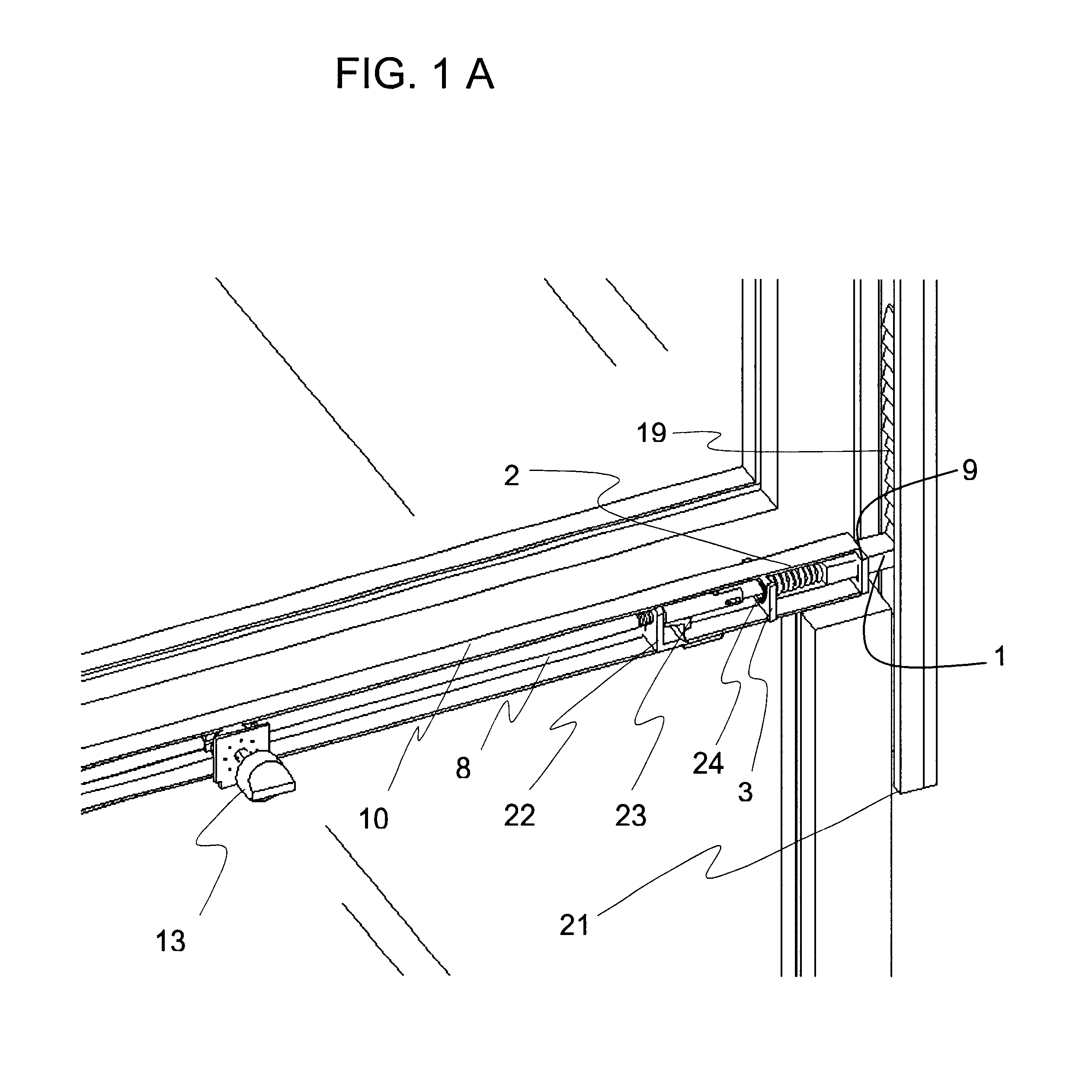
The window latch system of FIG. 1 operates using a selector knob 13 that allows the window sash to be slid and locked into discrete positions along a window or door sash latch track 19 of the window frame 21. The latch system can be applied to existing sliding doors or windows and be integrated into new window system designs. The system is composed of four components that form the complete mechanism, i.e., a rotatable selector hub assembly, connecting rods, latch pin assemblies, and latch track.

The latching system mechanism, according to the present invention, is integrated into the top transverse rail 20 of the lower sash. Alternatively, the latching system can be enclosed in a rectangula...

fifth embodiment

FIG. 12 shows the present invention wherein the above-described latching system is adapted for use with a horizontally sliding glass door or window 60 having sashes. At least one sash is movable. The latching system has a knob 13 on the meeting rail 20 on the movable sash of the sliding glass door or window, a latch track 19, and a door / window frame 21. Typically, the latch system for the sliding glass door would not have the tilt / pivoting mode.


PUM


Abstract

A sliding latch and locking mechanism, for windows and doors, whereby the latching mechanism provides a means for discrete position retention of a sliding window or door and provides an increased measure of security. The latching system combines four modes of operation i.e. lock, close only, raise (free sliding), and tilt to provide angular pivoting of window sash, that allow three levels of security, i.e. fully locked, close only with discrete positions maintained, and raise or lower without discrete positions maintained (free sliding). The latching system security levels are accomplished by means of a selector knob positioned to the desired mode of operation. Also, a mechanism is integrated to provide interlocking in the fully closed position with the upper or adjacent window or door sash.

Description

I. FIELD OF THE INVENTIONThe present invention relates to a sliding latch for windows and doors.II. BACKGROUND OF THE INVENTIONLocking mechanisms for sash windows are known in which, in the closed position, the handle of the locking mechanism engages an opposing receiving element affixed to the adjacent rail of the other window sash. Such latch mechanisms are effective for maintaining a window in a closed position, but are ineffective for holding the window in an intermediate partially open locked position.This invention arises from a long standing need to allow a window to remain in a position from fully closed to fully open while not allowing the opening to be increased in size from an exterior vantage point. However, the opening can decrease in size, while in a retained unlocked position, thereby providing increased security of an interior home or building by an unsuspecting intruder.The most common need is for sliding casement windows and doors, however the invention can be appl...

Claims


Application Information

Patent Timeline
Patent Type & Authority Patents(United States)
IPC IPC(8): E05D15/16E05D15/22E05C17/62E05C9/00E05C17/00E05B65/08E05C9/04E05B15/00
CPCE05B65/0876E05C9/043E05C17/62E05D15/22E05B15/0053Y10S292/20Y10S292/47Y10S292/53E05Y2900/148E05Y2900/132Y10T292/0806Y10T292/0836Y10T292/0844
Inventor ELLIOTT, GORDON W.
Owner ELLIOTT GORDON W
Why Eureka
Try Eureka