Elevated crane support system and method for elevating a lifting apparatus

a technology of lifting apparatus and crane support, which is applied in the direction of drilling pipes, caissons, artificial islands, etc., can solve the problems of limiting the working water depth of the vessel, occupying valuable deck space, and getting legs, and achieves enhanced capabilities and space efficiency.

Inactive Publication Date: 2003-08-19
THE LEVINGSTON
View PDF11 Cites 24 Cited by
  • Summary
  • Abstract
  • Description
  • Claims
  • Application Information

AI Technical Summary

Benefits of technology

The present invention contemplates a lift crane and support-structure-system which provides space efficiency in the form of an elevated support above the deck but with more enhanced capabilities than tubular tower arrangements and deck mounted cranes.
The combined jack-house / crane tub design allows one to support a crane above the deck in a stable manner independent of the leg situated there through, so as to provide a superior structural support for the lift crane, while providing ample space within the jack-house for the jacking units. The combined jack-house / crane tub support structure thereby affords significant space savings upon the deck of the platform, while providing enhanced support of the lift crane.
Another objective of the present invention is to provide a lift crane support structure which supports a lift crane above the surface of the deck but with greater structural stability and capacity than other prior art designs.

Problems solved by technology

The drawbacks of this mounting method have been both using up valuable deck space and the legs getting in the way of the movement of the hook load.
Lift cranes employing a tubular tower arrangement are limited to the maximum diameter of cylindrical pipe leg vessel designs thus limiting the working water depth of the vessel.

Method used


Image

  • Elevated crane support system and method for elevating a lifting apparatus
  • Elevated crane support system and method for elevating a lifting apparatus
  • Elevated crane support system and method for elevating a lifting apparatus

Examples


Embodiment Construction

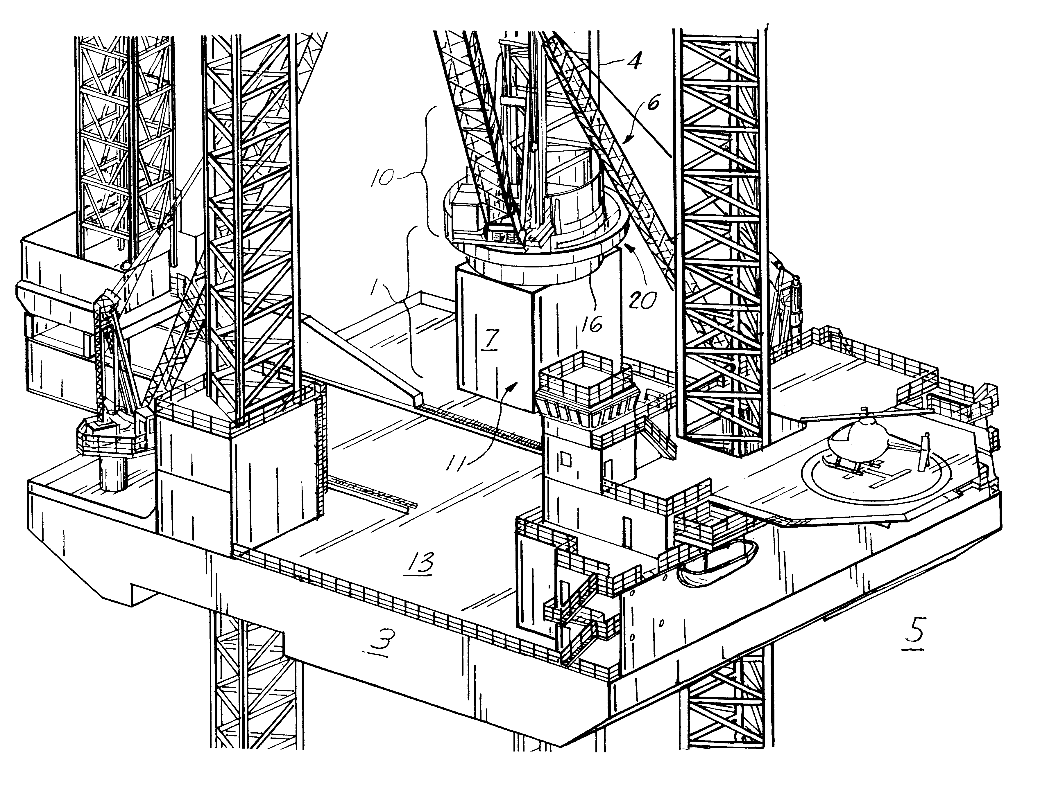
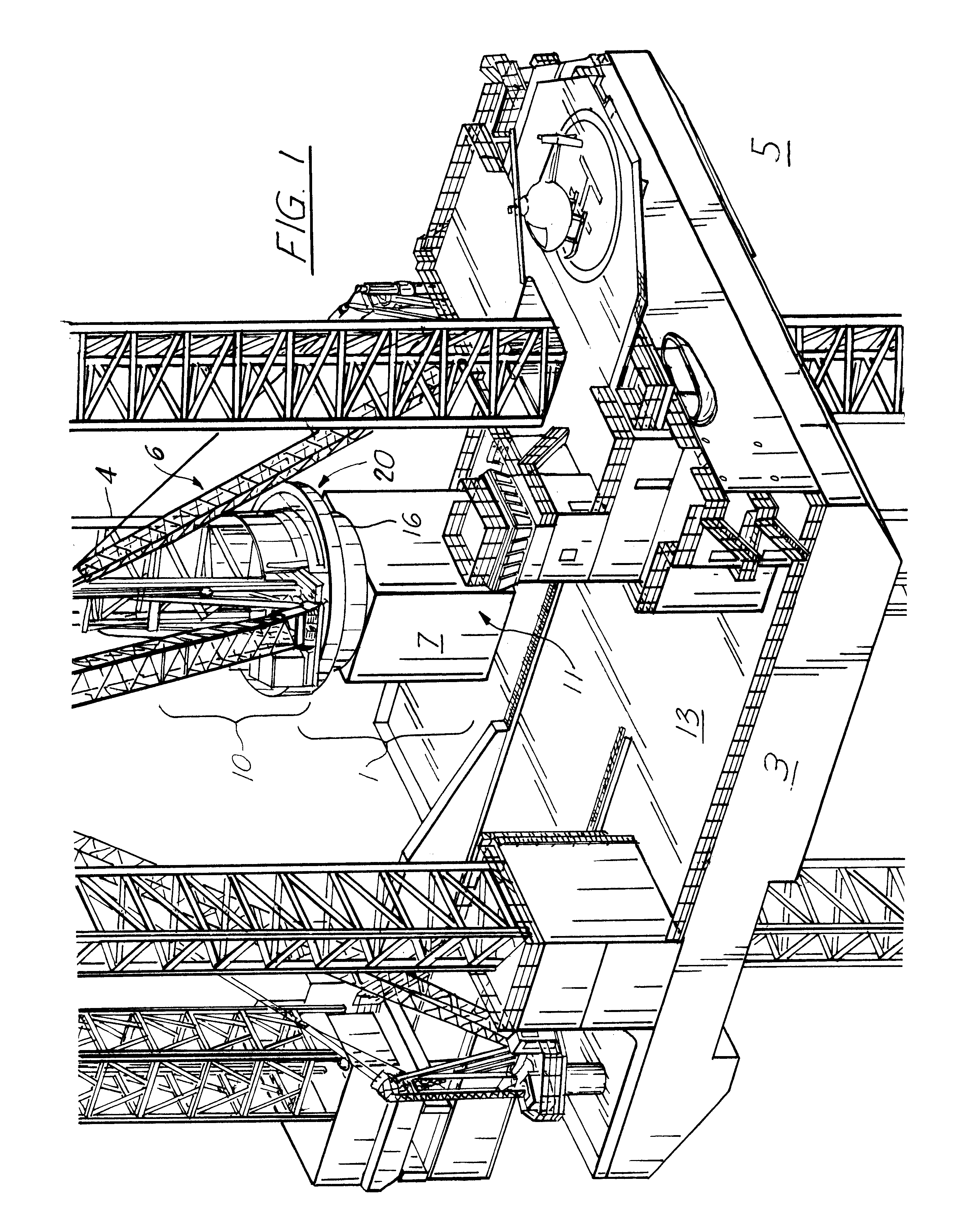
Referring to FIG. 1 of the drawings, the lift crane support structure / jack-house 1 of the present invention is integrated into the deck 13 of a vessel 3 such as a jack-up drilling rig, jack-up service vessel, barge, platform, or the like having legs 4 configured to engage the water bottom 5 to lift the vessel above the water level, the legs 4 passing through vertical, enveloped passageways 6 formed through the deck and hull of the vessel. To facilitate lifting or lowering of the legs 4, jacking units 11, 11' are provided, generally within a jack-house 7.

In order to provide a more stable, elevated platform for a crane to operate on the vessel, while lessening deck space requirements, the jack-house of the present invention is reinforced to allow the placement of a crane tub 16 emanating from the top of the jack-house, which crane tub has at its distal end a flange 20 for the rotatable engagement of a crane 10 thereupon.

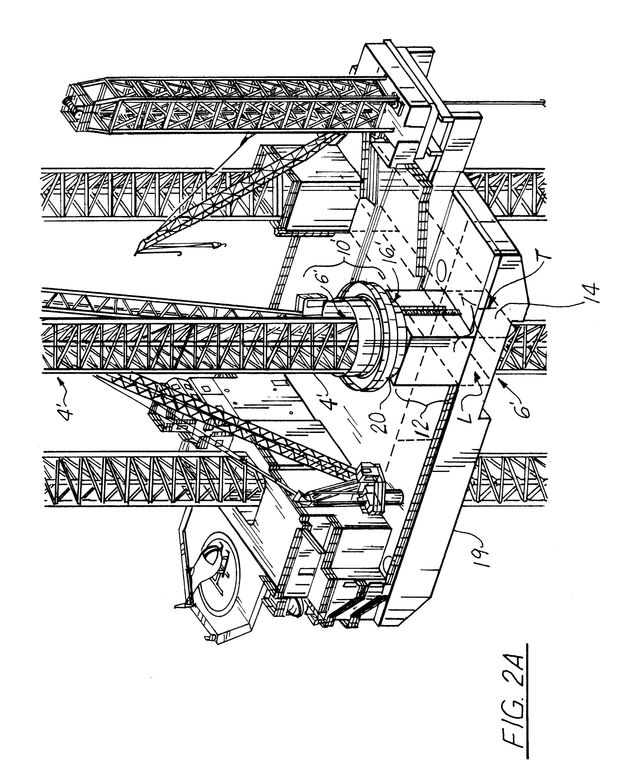
Continuing with FIGS. 2A-2C, 3A-3C, and 4A-4C, the jack-house 7',...


PUM


Abstract

A support structure for supporting a lift crane, and in particular to a lift crane jack-up structures, including rigs, platforms, barges, boats or the like, wherein the lift crane is positioned about a leg of the jack-up structure atop the jack-house. The preferred embodiment of the present invention contemplates a system for elevating a lift crane above the deck and about the leg of the jack-up structure, without relying upon the leg for structural support. A structurally reinforced jack-house having jacking units interfacing with the leg is provided at the deck of the vessel the jack-house configured to engage and support a crane tube column upon the roof of the jack house, which crane tube column in turn has situated thereupon the lift crane.

Description

The present invention relates to a support structure for supporting a lift crane and in particular to lifting cranes for use on jack-up type drilling rigs, lift boats, platforms, boats and the like, wherein the lift crane is positioned about a leg(s) of the jack-up structure atop the jack-house or yoke assembly.The preferred embodiment of the present invention contemplates a system for elevating a lift crane above the deck and about the leg of the jack-up structure, without relying upon the leg for structural support, unlike king post-type design lift cranes. A structurally reinforced jack-house or yoke assembly having jacking units interfacing with the leg, is provided at the deck of the vessel. The jack-house or yoke assembly is configured to engage and support a crane tub upon the top of the jack-house or yoke assembly, which crane tub has situated thereupon the lift crane.The structurally designed jack-house or yoke assembly allows one to support a crane above the deck in a stab...

Claims


Application Information

Patent Timeline
Patent Type & Authority Patents(United States)
IPC IPC(8): B66C23/52B66C23/00E02B17/08E02B17/00B66C23/53
CPCB66C23/52E02B17/08E02B17/021E02B2017/006
Inventor SANDERS, RONALD E.BUTLER, PAUL
Owner THE LEVINGSTON
Why Eureka
Try Eureka