Paint mixer

a paint mixer and motor technology, applied in the direction of mixer accessories, mixers, other chemical processes, etc., can solve the problems of difficult maintenance or repair, difficulty in service of current available paint mixers, and inability to meet the needs of painting, so as to improve stability, facilitate removal or installation, and improve the effect of stability

Inactive Publication Date: 2003-09-02
FLUID MANAGEMENT LLC
View PDF12 Cites 29 Cited by
  • Summary
  • Abstract
  • Description
  • Claims
  • Application Information

AI Technical Summary

Benefits of technology

In a refinement, the base further comprises a bottom surface that has three spaced apart adjustable supports for improved stability during operation. It has been found that the use of three spaced apart supports provides improved stability over the use of four spaced apart supports.
In yet a further refinement, the base further comprises a front wall having a lower end. The lower end of the front wall comprises a recess. The recess enables an operator or a service technician to place his or her toes within the recess to get closer to the mixer during movement of the mixer. To facilitate movement of the mixer, a handle may be included on the front wall of the cabinet so that the operator or technician may grasp the handle, tilt the mixer backwards onto the casters for easy movement of the mixer about the store floor.

Problems solved by technology

Despite the longtime use of these devices, prior art paint mixers suffer from a number of deficiencies.
Specifically, currently available paint mixers are difficult to service because the motor, belt and other working components of the mixer are difficult to access and, accordingly, difficult to repair or maintain.
As a result, the maintenance process is complicated and consumes additional time due to the problems in accessing the working components.
Because a paint mixer imparts a violent vibrating or shaking motion to the can or pail of paint, paint mixers require periodic maintenance and therefore the maintenance of paint mixers is both time consuming and costly to the retailer.
If the adjustment to one of the legs or foot pads is off, the paint mixer will rock back and forth during operation thereby causing the paint mixer to move across the floor.
Further, typical paint mixers are heavy and difficult to move.
Typical paint mixers do not have rollers or casters and therefore they can only be moved within a store using a hand cart or fork lift.
In either case, adjustment of the support legs and movement of the mixer is time consuming and cumbersome.
Further, many paint containers may leak during the violent shaking that occurs during operation of the paint mixer.
The accumulation of paint inside the mixer is aesthetically unappealing and results in substantial build-up over time.
The accumulated paint must eventually be removed which, again, is time consuming and therefore costly because the interior of prior art mixers is not easily accessible.

Method used


Image

  • Paint mixer
  • Paint mixer
  • Paint mixer

Examples


Embodiment Construction

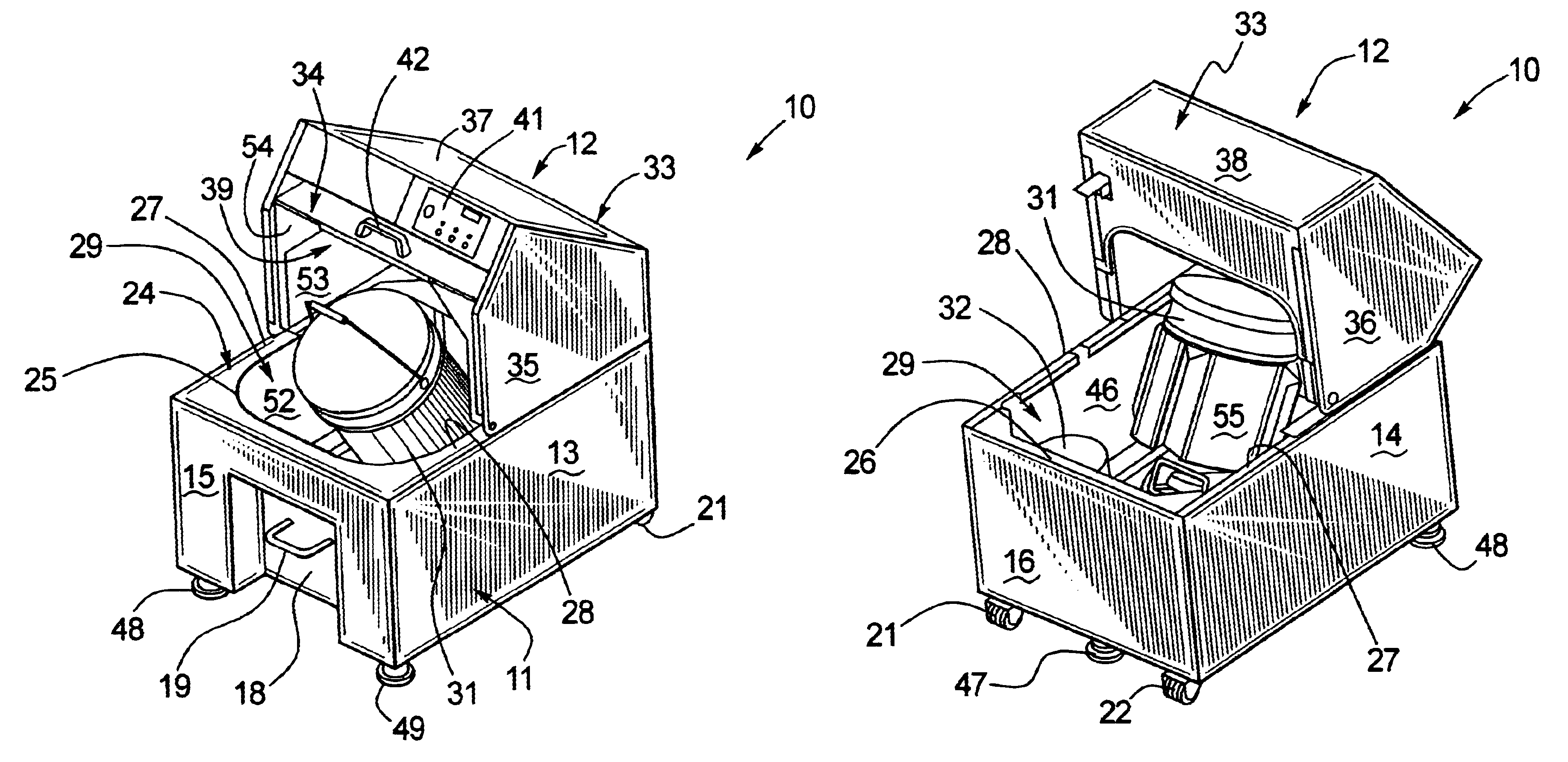
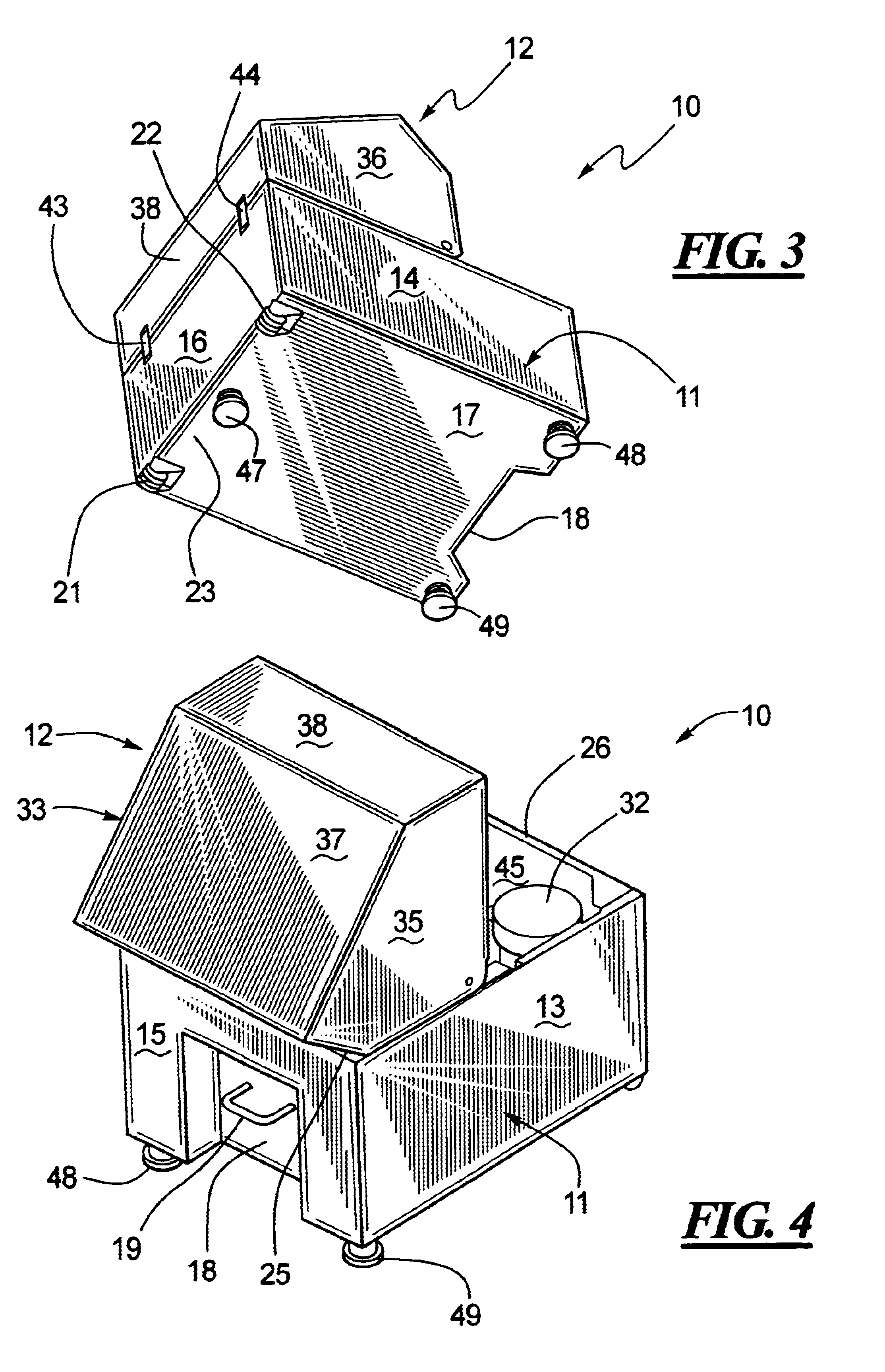
Referring first to FIG. 1, the paint mixer 10 includes a base 11 and an upper cabinet 12. In the embodiment illustrated in FIG. 1, the base 11 includes a four walled rectangular configuration including sidewalls 13, 14 (see also FIG. 2), front wall 15 and rear wall 16. The base 11 also includes a bottom wall 17 as shown in FIG. 3. The front wall 15 of the base 11 includes a recess 18 which can be used to accommodate an operator's toes or feet during movement of the mixer 10. Specifically, the operator can grasp the handle 19 mounted on the front wall 15 of the base 11, pull the front end of the mixer upward so that the weight of the mixer is shifted to the two casters 21, 22 disposed along the rear end 23 of the bottom wall 17. Use of the recess 18 enables the operator to stand closer to the mixer 11 during the moving process.

The base 11 also includes a top ledge 24 which can be considered to have a front section 25, a rear section 26 (see FIG. 4) and two connecting middle sections ...


PUM


Abstract

An improved paint mixer is disclosed which includes a base and an upper cabinet pivotally connected to the base. The upper cabinet can be pivoted from a first rearward position which provides access to a front section of the base and a second forward position which provides access to a rear section of the base. As a result, both the front and rear section of the base are easily accessible for service, maintenance, and cleaning. A support system that includes three adjustable legs provides improved support and stability. Casters disclosed at the rear end of the bottom of the base along with a recessed wall of the base and a handle disposed at the front of the base make it easier to move and / or relocate the mixer. Non-stick coatings in the form of a paint-resistant coating or an anti-graffiti coating to the inside surfaces of the mixer facilitate the removal of accumulated paint.

Description

A motorized paint mixer is disclosed. More specifically, a paint mixer that includes an upper cabinet that is pivotally connected to the base is disclosed which enables the upper cabinet to pivot between two positions thereby providing improved access to the motor, belt and other working components of the paint mixer for service and maintenance.BACKGROUND OF THE RELATED ARTMotorized paint mixers are known. Specifically, typical motorized paint mixers include a base structure having a motor, belt and other components used to rapidly shake a can or pail of paint so that the paint can be sold to a customer in a thoroughly mixed condition. Most retail paint stores or hardware stores utilize one or more of these devices. Despite the longtime use of these devices, prior art paint mixers suffer from a number of deficiencies.Specifically, currently available paint mixers are difficult to service because the motor, belt and other working components of the mixer are difficult to access and, a...

Claims


Application Information

Patent Timeline
Patent Type & Authority Patents(United States)
IPC IPC(8): B01F11/00B01F15/00
CPCB01F11/0008B01F15/0074B01F15/00922Y10S366/605B01F31/201B01F35/421B01F35/10
Inventor BLAKEMAN, II, ROBERT D.MILLER, WILLIAM A.KOSSEL, JOHN MARTIN
Owner FLUID MANAGEMENT LLC
Why Eureka
Try Eureka