Optical repeating device with monitoring function

a technology function, which is applied in the field of optical repeating device with a monitoring function, can solve the problems of difficult to achieve downsizing of optical repeating device, and achieve the effect of simplifying and downsizing the construction

Inactive Publication Date: 2003-09-02
SANKOSHA CORP +1
View PDF13 Cites 13 Cited by
  • Summary
  • Abstract
  • Description
  • Claims
  • Application Information

AI Technical Summary

Benefits of technology

to simplify and downsize the construction of a housing by providing optical branching means for branching off, and reflecting a portion of a lightwave signal propagating through first optical propagation means and second optical propagation means in a given direction, and by disposing photodetection means such as PDs on the optical axis of the lightwave signal reflected, and also t

Problems solved by technology

However, with the conventional optical repeating device, the following problems have been encountered.
That is, since the conventional optical repeating device comprises in combination a plurality of optical devices such as the optical branches, PDs, and so forth, there is a tendency of

Method used


Image

  • Optical repeating device with monitoring function
  • Optical repeating device with monitoring function
  • Optical repeating device with monitoring function

Examples


first embodiment (

FIGS. 1 and 2)

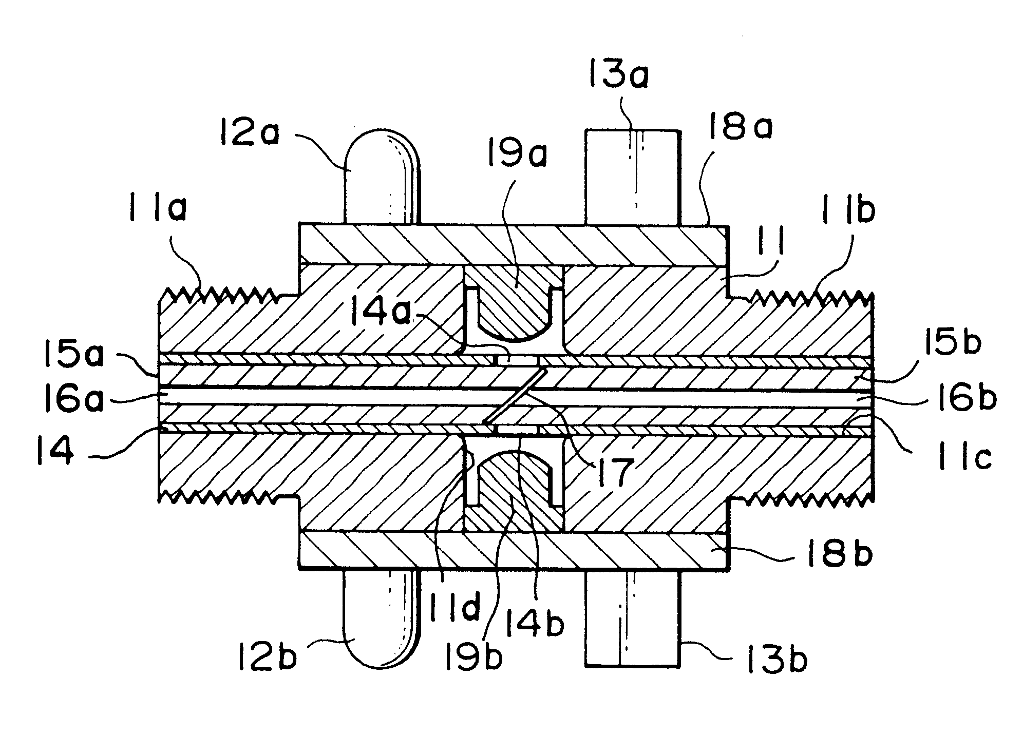
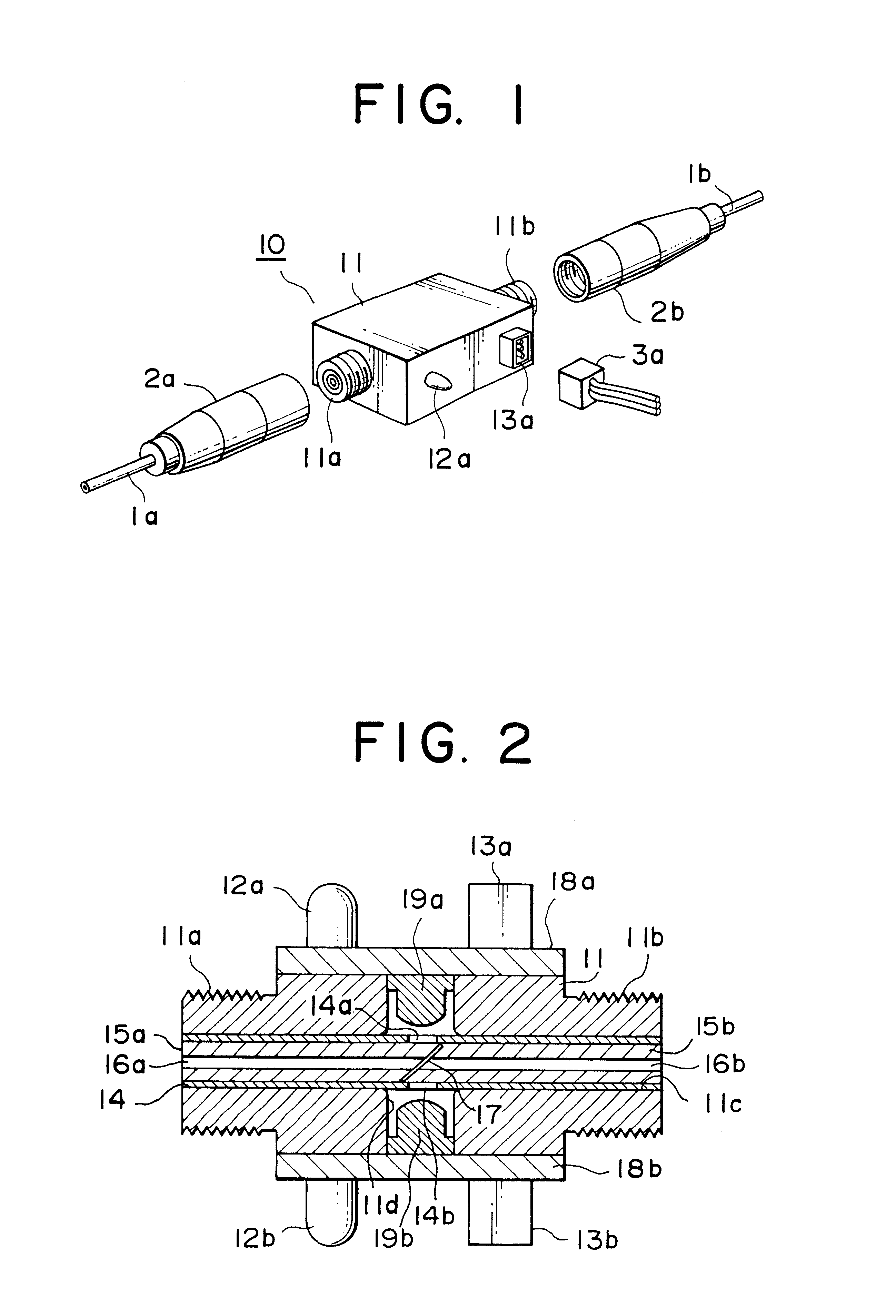
As shown in FIG. 1, an optical repeating device 10 with a monitoring function is a device adapted to one communication line, and is assembled into, and formed integrally with a housing 11 of a transmissive type, having precise--and rugged-build, formed of precise and substantial material such as engineering plastics, and the like by, for example, die casting. The housing 11 is provided with a connection 11a for connection with an optical connector 2a on the side of an optical fiber 1a, and a connection 11b for connection with an optical connector 2b on the side of an optical fiber 1b, which are formed at opposite end faces thereof, respectively, so as to be inserted between the optical fibers 1a, 1b for transmitting a lightwave signal, that is, the object to be detected. These connections 11a, 11b are disposed in a line, and are, for example, 10 mm in diameter, having a threaded structure up to a predetermined length, so as to match with the coupling type of the optica...

second embodiment (fig.3)

Second Embodiment (FIG. 3)

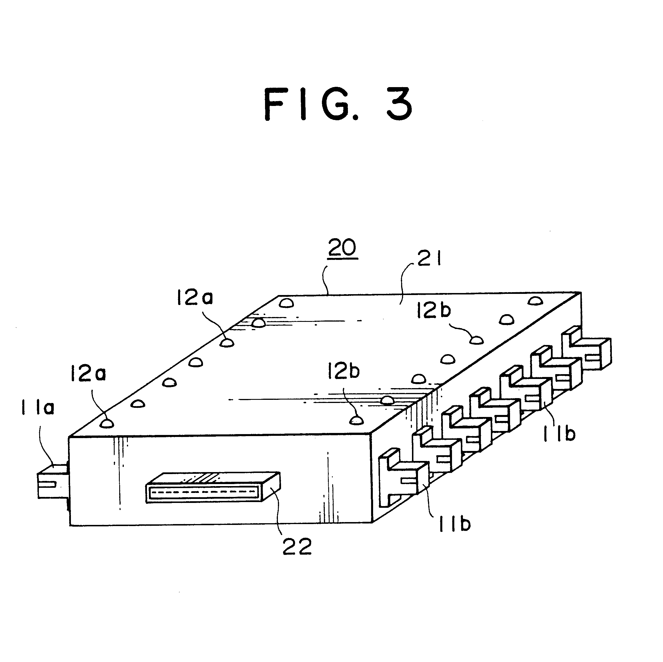
With a second embodiment of an optical repeating device 20 with a monitoring function according to the invention as shown FIG. 3, parts in common with those in FIGS. 1 and 2, showing the first embodiment of the invention, are denoted by common reference numerals.

The optical repeating device 20 with the monitoring function, shown in FIG. 3, is a device adapted to a plurality of communication lines, and a plurality of the optical repeating device 10 with the monitoring function, as shown in FIGS. 1 and 2, are placed in parallel with each other, and are housed in one cabinet 21. A plurality of connections 11a, 11b of fit-in type, corresponding to the plurality of communication lines, are attached to side faces of the cabinet 21, on opposite sides, respectively. The upper surface of the cabinet 21 is provided with a plurality of LEDs 12a, 12b, and another side face of the cabinet 21 is provided with a common connector 22 for supplying electric power from a powe...


PUM


Abstract

An optical repeating device with a monitoring function comprises first optical propagation means for propagating a lightwave signal through an optical transmission line, second optical propagation means butted against the first optical propagation means, for propagating the lightwave signal, optical branching means provided on a butting face between the first optical propagation means, and the second optical propagation means, and photodetection means. All the means described are assembled into a housing, and integrated therewith. Consequently, it is possible to downsize the optical repeating device with the monitoring function. A large portion of the lightwave signal propagated between the first optical propagation means and the second optical propagation means is allowed to pass through the optical branching means, however, a portion of the lightwave signal is reflected in a given direction by the optical branching means. A lightwave signal reflected is detected by the photodetection means, and is converted into an electric signal. When the electric signal as converted is displayed by, for example, display means, it is possible to check visually whether or not the lightwave signal is transmitted through the optical transmission line.

Description

1. Field of the InventionThe present invention relates to an optical repeating device with a monitoring function to be inserted in an optical transmission line such as optical fibers, and so forth for detecting lightwave signals being transmitted through the optical transmission line.2. Description of the Related ArtConventional technologies in this field have been described in, for example, the following documents.Document 1: Japanese Patent Publication No. H3-60090;Title of the Invention; Optical ConnectorPublication Date; Sep. 12, 1991Document 2: Japanese Utility Model Registration No. 2586555;Title of the Invention; Optical Demultiplexer-MultiplexerRegistration Date; Oct. 2, 1998A technology related to an optical connector for connecting two lengths of optical fibers with each other is described in Document 1. The optical connector comprises a pair of ferrules, each attached to the tip of the respective lengths of the optical fibers to be connected with each other and having a p...

Claims


Application Information

Patent Timeline
IPC IPC(8): G02B6/34G02B6/24G02B6/42G02B6/38G02B6/28
CPCG02B6/241G02B6/4214G02B6/3822G02B6/3845G02B6/421G02B6/424G02B6/4284
Inventor WATANABE, KATSUMIKAWAHARA, FUMIKAOKAWA, TAKAYUKI
Owner SANKOSHA CORP
Why Eureka
Try Eureka