Apparatus, system and method for separating liquids

a technology of apparatuses and liquids, applied in the field of apparatuses for liquid separation, can solve the problems of complex apparatuses, mechanical complexity, and wear, bulkiness and adjustment, and achieve the effect of maximizing the resistance of membranes to clogging thereo

Inactive Publication Date: 2003-09-02
PROFILTRA
View PDF10 Cites 54 Cited by
  • Summary
  • Abstract
  • Description
  • Claims
  • Application Information

AI Technical Summary

Benefits of technology

selecting the best oscillatory conditions (the oscillation amplitude and frequency) for the liquid in the apparatus for membrane separation from the standpoint of minimization of membrane clogging, which will be dependent on properties of these membran...

Problems solved by technology

However, it is well known that the micro-filtration stage that has to help avoid the nano-filtration membrane clogging will itself constitute a stage to cause a clogging problem.
The system based on the two last inventions are very bulky and complicated.
The above modules, though complicated in terms of composition, may easily and quickly be attached to filtration system and detached from the same.
On the other hand, these apparatuses are mechanically complicated and experience problems of wear, bulkiness and adjustment particularly as it concerns their rotating parts.
They frequently require ...

Method used


Image

  • Apparatus, system and method for separating liquids
  • Apparatus, system and method for separating liquids
  • Apparatus, system and method for separating liquids

Examples


first embodiment

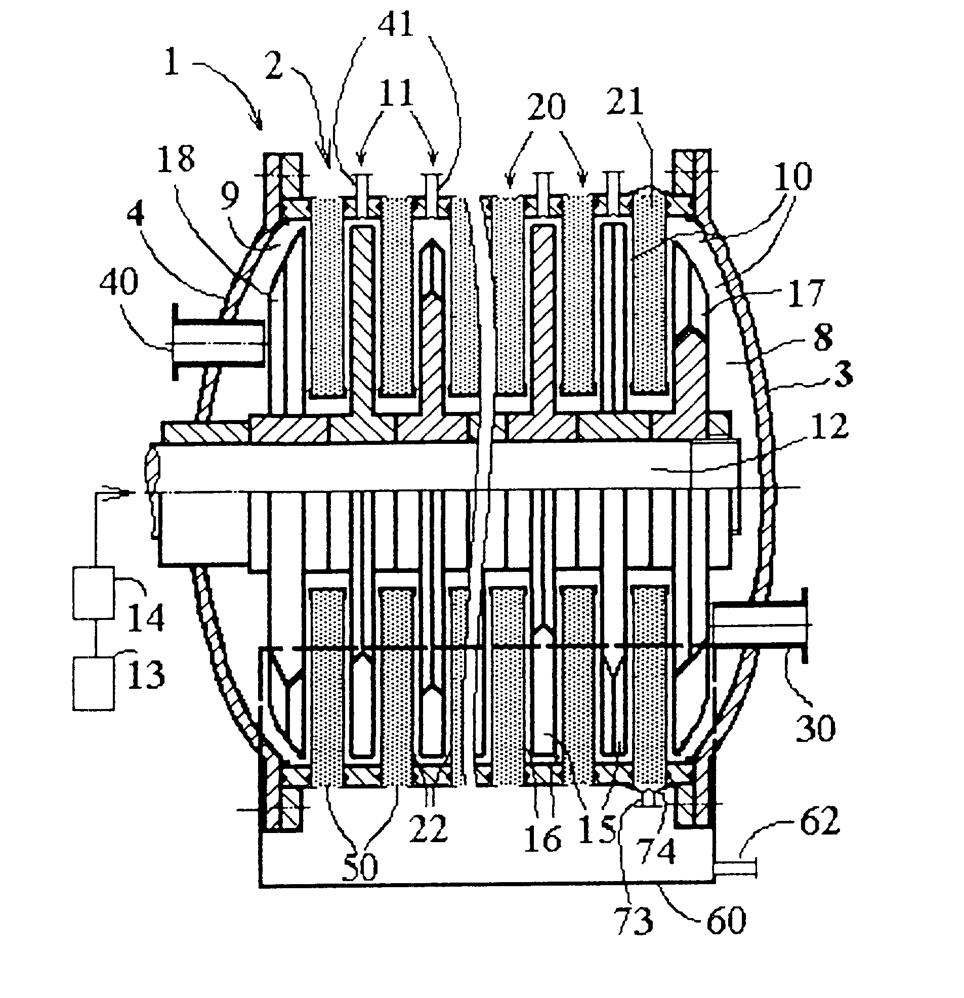
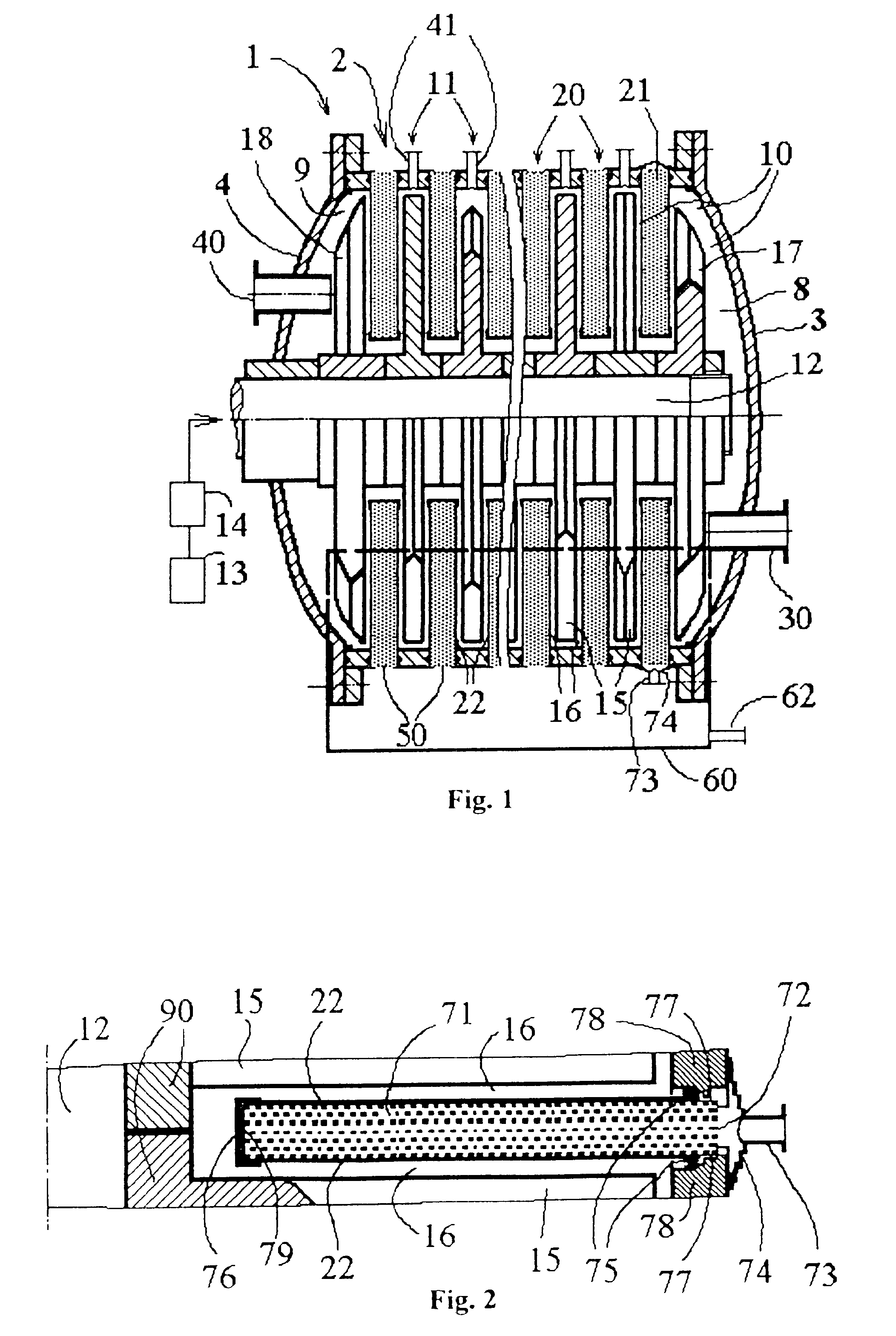
Referring to FIG. 1, the apparatus for membrane separation is described. Apparatus for membrane separation 1 includes fixed cylindrical housing 2 separated with membranes into two compartments. First compartment 10 contains the liquid, second compartment 20 contains the treated liquid, i.e. the permeate or filtrate. The apparatus for membrane separation includes:

at least one common liquid inlet means 30 mounted on first end wall 3, between shaft 12 and the outer edge of this end wall, said apparatus 30 being connected to extreme liquid inlet cell 8;

at least one common liquid outlet means 40 mounted on second end wall 4, between shaft 12 and the outer edge of this end wall, said apparatus 40 being connected to extreme liquid outlet cell 9;

at least one permeate outlet means 50 and / or 73.

Each intermediate cell 11 of the apparatus for membrane separation has at least one peripheral liquid outlet means 41. The ratio of apparatus 40 liquid flow rate to a sum of the rates of flow through l...

second embodiment

FIG. 5 provides a schematic representation of the apparatus for membrane separation. This figure uses the designations of FIG. 1 to identify the parts which are common for the two embodiments of the apparatus for membrane separation.

In the second embodiment, the apparatus for membrane separation includes axial liquid inlet means 31; being connected to hollow shaft 19, this apparatus is located in first end wall 3 of apparatus for membrane separation 1. To introduce the liquid into each cell of the apparatus for membrane separation, use if made of radial bores 32 made in the shaft wall at the level of each permeate chamber and radial bores 33 made in central ring 90 of each impeller. The impellers are so set on the shaft that the aforementioned bores in the shaft wall and in the central rings of the impellers coincide with each other. The liquid leaves the apparatus for membrane separation via a common liquid outlet means 40 where its flow is caused to oscillate by rotation of extrem...

third embodiment

FIG. 6 provides a schematic representation of the apparatus for membrane separation. This figure uses the designations of FIGS. 1 and 5 to identify the parts which are common for the three embodiments of the apparatus for membrane separation.

In the third embodiment, the apparatus for membrane separation includes two liquid inlet means 30 and 31. This apparatus for membrane separation synthesizes the first and second embodiments of the invention and can be used to ensure better maintenance of the ratio of the liquid flows passing through each cell in the sequential manner and parallel manner.

Although FIGS. 1, 5, and 6 represent horizontal apparatus for membrane separationes (having a horizontal housing and shaft) the apparatus for membrane separation can be of vertical design which is presented by way of example in FIG. 7 (for the third embodiment). This figure uses the designations of FIGS. 1, 5 and 6 to identify the parts which are common for the three embodiments of the horizontal...


PUM

PropertyMeasurementUnit
Thicknessaaaaaaaaaa
Thicknessaaaaaaaaaa
Thicknessaaaaaaaaaa

Abstract

The subject of the invention is an apparatus, system and process for liquid separation by reverse osmosis, nano-, ultra- and micro-filtration under the joint action of the differential pressure built up on the either side of the membrane (22) located in the apparatus for membrane separation (1), continuous rotation of the body (15, 17, 18) in the immediate proximity to the selective layer of the said membrane, oscillation of the liquid flow, caused by the means (15, 17, 18) and induced vibration of the said membranes. The superposition of the said continuous rotary movements, liquid oscillations and membrane vibrations on each other result in the reduction of membrane clogging with the substances being retained.

Description

This application is the U.S. national-phase application of PCT International Application No. PCT / FR98 / 02475.Field of invention consists in treatment, separation and cleaning of liquids. Videlicet, the present invention relates to an apparatus for membrane separation that treats liquids by extracting suspended, emulsified and / or dissolved substances (mineral and organic ones) out of the said liquids. The same relates to a system and process of liquid separation.The apparatus for membrane separation allows to obtain two flows of liquids such as:a) flow of permeate or filtrate fully or partly free from suspended, emulsified and or dissolved substances (mineral and organic ones). This flow represents the major part of the liquid being treated;b) flow of concentrate or retentate enriched with suspended, emulsified and or dissolved substances.The present invention also relates to treatment of liquids containing chemicals, microbiological and pharmaceutical substances, foodstuffs that shal...

Claims


Application Information

Patent Timeline
IPC IPC(8): B01D65/08B01D63/16B01D65/00B01D63/08
CPCB01D63/16B01D65/08B01D2321/2058
Inventor JITARIOUK, NIKOLAI
Owner PROFILTRA
Why Eureka
Try Eureka