
Multi-channel non-invasive tissue oximeter

a tissue oximeter and multi-channel technology, applied in the field of multi-channel non-invasive tissue oximeters, can solve the problems of difficult signal-to-noise problems, distortion and/or obscurity of brain examination data, and extremely low-level electrical signal outputs of detectors for analysis

Inactive Publication Date: 2003-09-02
TYCO HEALTHCARE GRP LP
View PDF21 Cites 320 Cited by
  • Summary
  • Abstract
  • Description
  • Claims
  • Application Information

AI Technical Summary

Benefits of technology

The present invention results from the new insights into and increased understanding of the human brain referred to in the preceding paragraph, and provides a methodology and apparatus for separately (and preferably simultaneously) sensing and quantitatively determining brain oxygenation at a plurality of specifically different locations or regions of the brain, particularly durin...

Problems solved by technology

This information was not previously available, despite its great importance, since there really is no detectable arterial pulse within brain tissue itself with respect to which pulse oximetry could be utilized even if it could be effectively utilized in such an interior location (which is very doubtful), and this determination therefore requires a substantially different kind of apparatus and determination analysis.
In addition, there are a number of uniquely complicating factors, including the fact that there is both arterial and venous vasculature present in the skin and underlying tissue through which the examining light spectra must pass during both entry to and exit from the brain, and this would distort and / or obscure the brain examination data if excluded in some way.
In addition, the absorption and scatter effects on the examination light spectra are much greater in the brain and its environment than in ordinary tissue, and this tends to result in extremely low-level electrical signal outputs from the detectors for analysis, producing difficult signal-to-noise problems.

Method used


Image

  • Multi-channel non-invasive tissue oximeter
  • Multi-channel non-invasive tissue oximeter
  • Multi-channel non-invasive tissue oximeter

Examples


Embodiment Construction

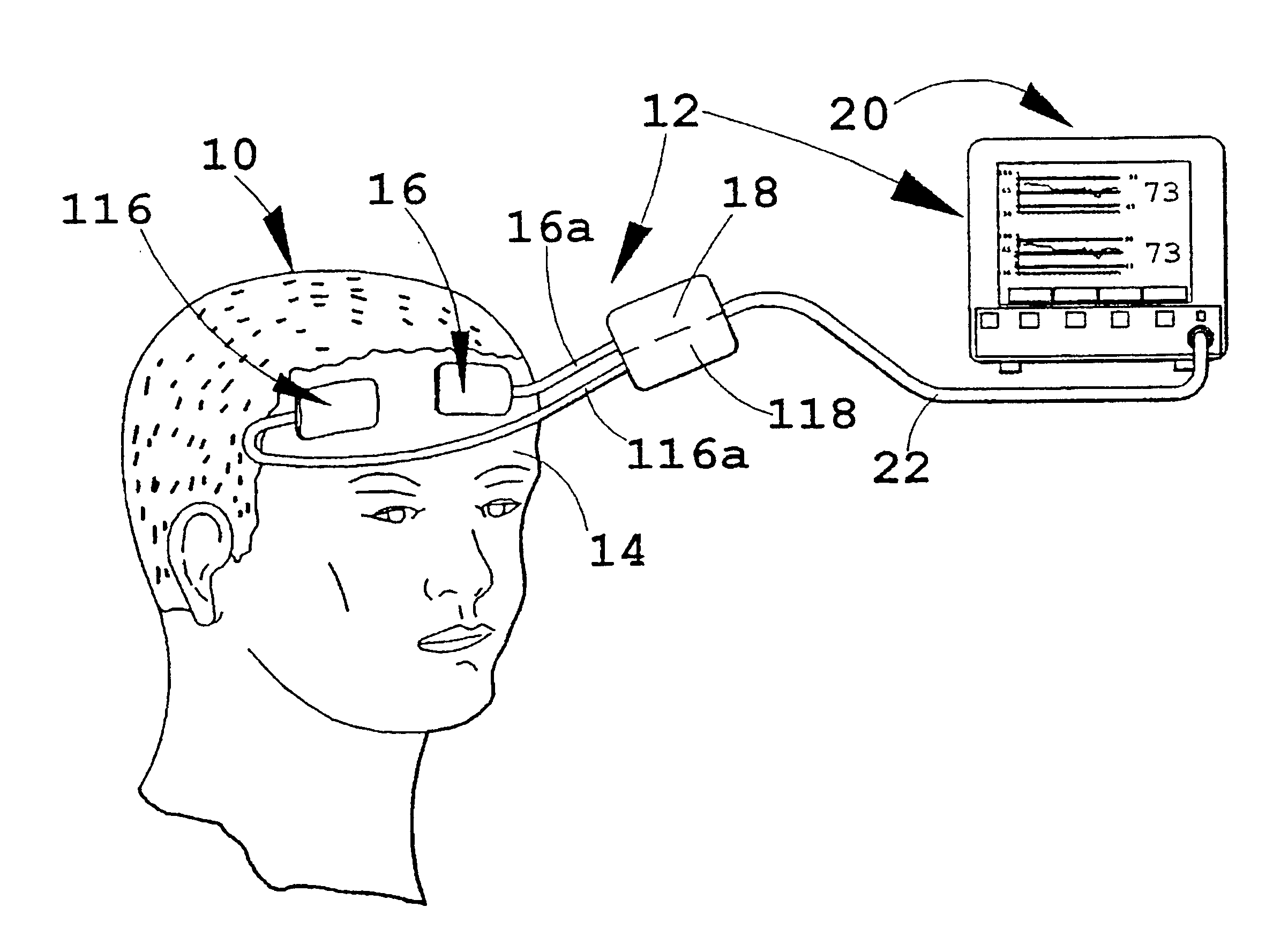
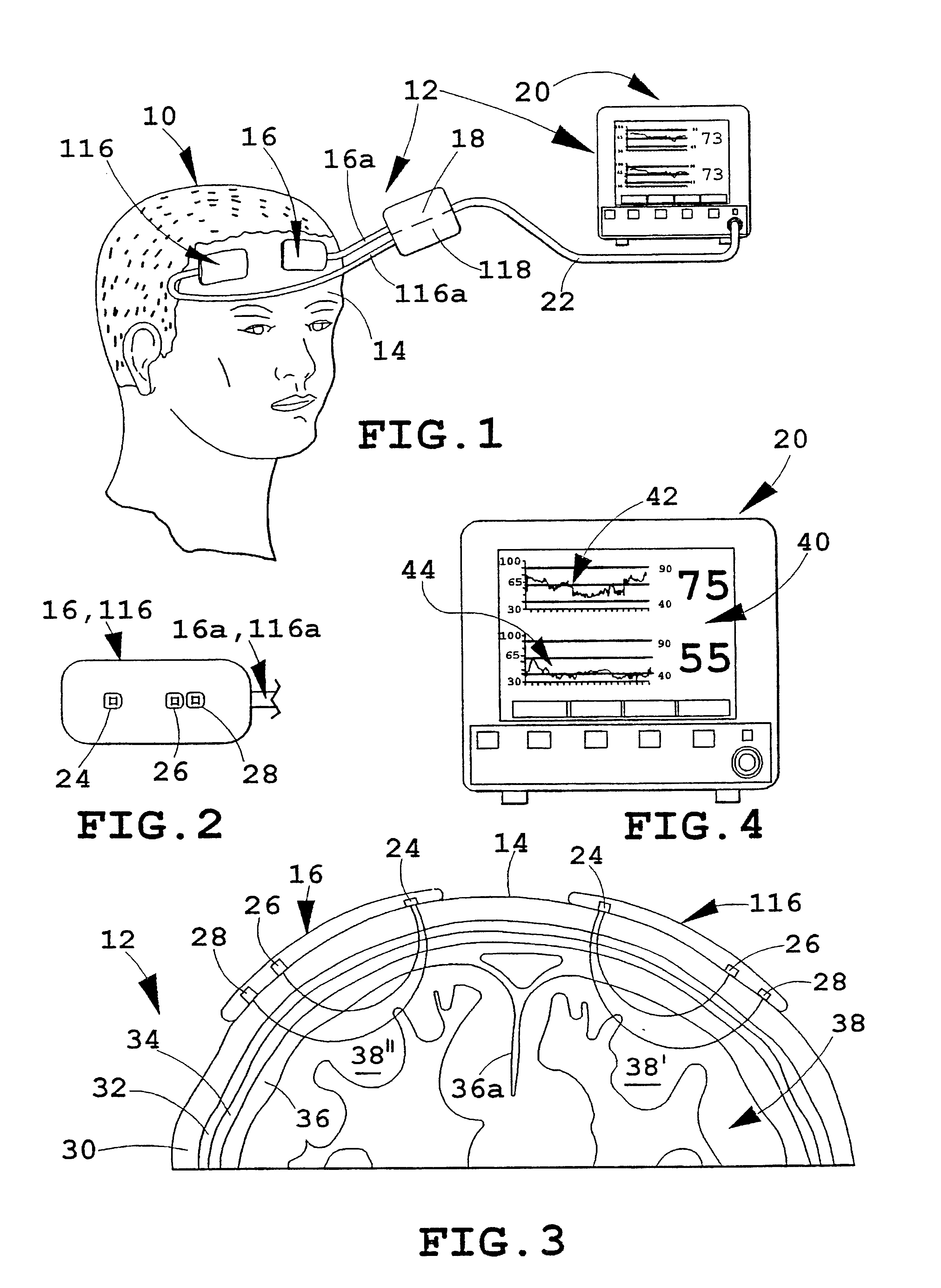
FIG. 1 depicts an illustrative patient 10 on whom an instrument 12 in accordance with the present invention is being employed. As illustrated, the forehead 14 of patient 10 has a pair of sensors 16, 116 secured to it in a bilateral configuration, i.e., one such sensor on each side of the forehead, where each may monitor a different brain hermisphere. Each of the sensors 16, 116 is connected to a processor and display unit 20 which provides a central control and processing station (sometimes hereinafter, referred to as the "oximeter") by a corresponding electrical cable 16A, 116A, which join one another at a dual-channel coupler / pre-amp 18, 118 and then (preferably) proceed to the control and processor 20 as an integrated, multiple-conductor cable 22. As will be understood, the electrical cables just noted include individual conductors for energizing light emitters and operating the related light detectors contained in sensors 16, 116, all as referred to further hereinafter and expla...


PUM


Abstract

A method and apparatus for spectrophotometric in vivo monitoring of blood metabolites such as hemoglobin oxygen concentration at a plurality of different areas or regions on the same organ or test site on an ongoing basis, by applying a plurality of spectrophotometric sensors to a test subject at each of a corresponding plurality of testing sites and coupling each such sensor to a control and processing station, operating each of said sensors to spectrophotometrically irradiate a particular region within the test subject; detecting and receiving the light energy resulting from said spectrophotometric irradiation for each such region and conveying corresponding signals to said control and processing station, analyzing said conveyed signals to determine preselected blood metabolite data, and visually displaying the data so determined for each of a plurality of said areas or regions in a comparative manner.

Description

This invention relates generally to in vivo spectrophotometric examination and monitoring of selected blood metabolites or constituents in human and / or other living subjects, e.g., medical patients, and more particularly to spectrophotometric oximetry, by transmitting selected wavelengths (spectra) of light into a given area of the test subject, receiving the resulting light as it leaves the subject at predetermined locations, and analyzing the received light to determine the desired constituent data based on the spectral absorption which has occurred, from which metabolic information such as blood oxygen saturation may be computed for the particular volume of tissue through which the light spectra have passed.A considerable amount of scientific data and writings, as well as prior patents, now exist which is / are based on research and clinical studies done in the above-noted area of investigation, validating the underlying technology and describing or commenting on various attributes...

Claims


Application Information

Patent Timeline
IPC IPC(8): A61B5/00A61B5/145A61B5/1455
CPCA61B5/14553A61B5/6814A61B5/14552A61B2562/04A61B2562/164
Inventor BARRETT, BRUCE J.GONOPOLSKY, OLEGSCHEUING, RICHARD S.
Owner TYCO HEALTHCARE GRP LP
Learn More