Constant velocity joint
a constant velocity joint and universal technology, applied in the direction of yielding couplings, rotary machine parts, couplings, etc., can solve the problems of limiting the size of a conventional constant velocity joint, the overall radial size of the joint is decreased, and the construction of both joints is rather complex. , to achieve the effect of compact constant velocity joints, reducing the overall radial size of the joints, and simplifying the geometry of contact surfaces and ball grooves
- Summary
- Abstract
- Description
- Claims
- Application Information
AI Technical Summary
Benefits of technology
Problems solved by technology
Method used
Image
Examples
first embodiment
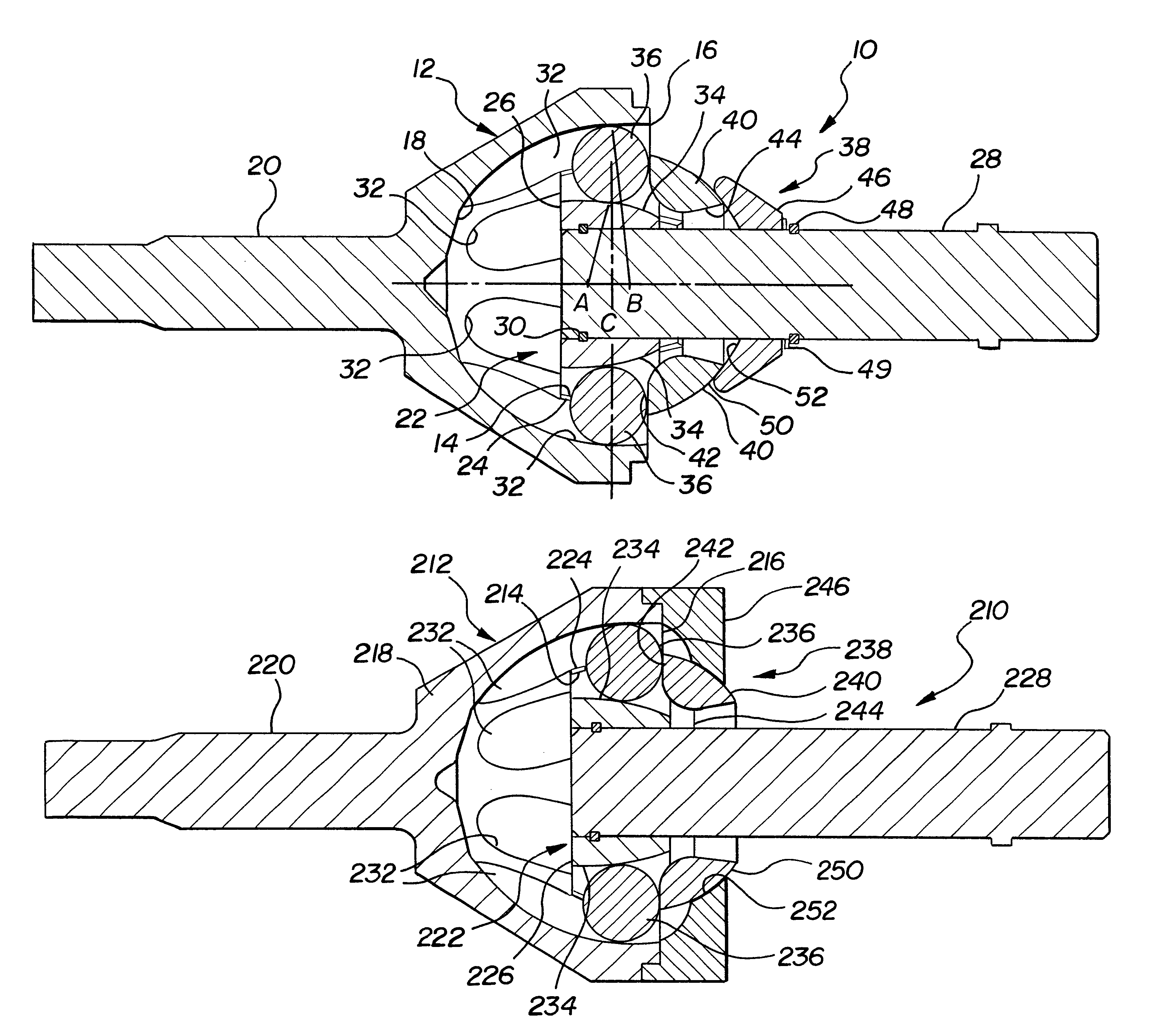
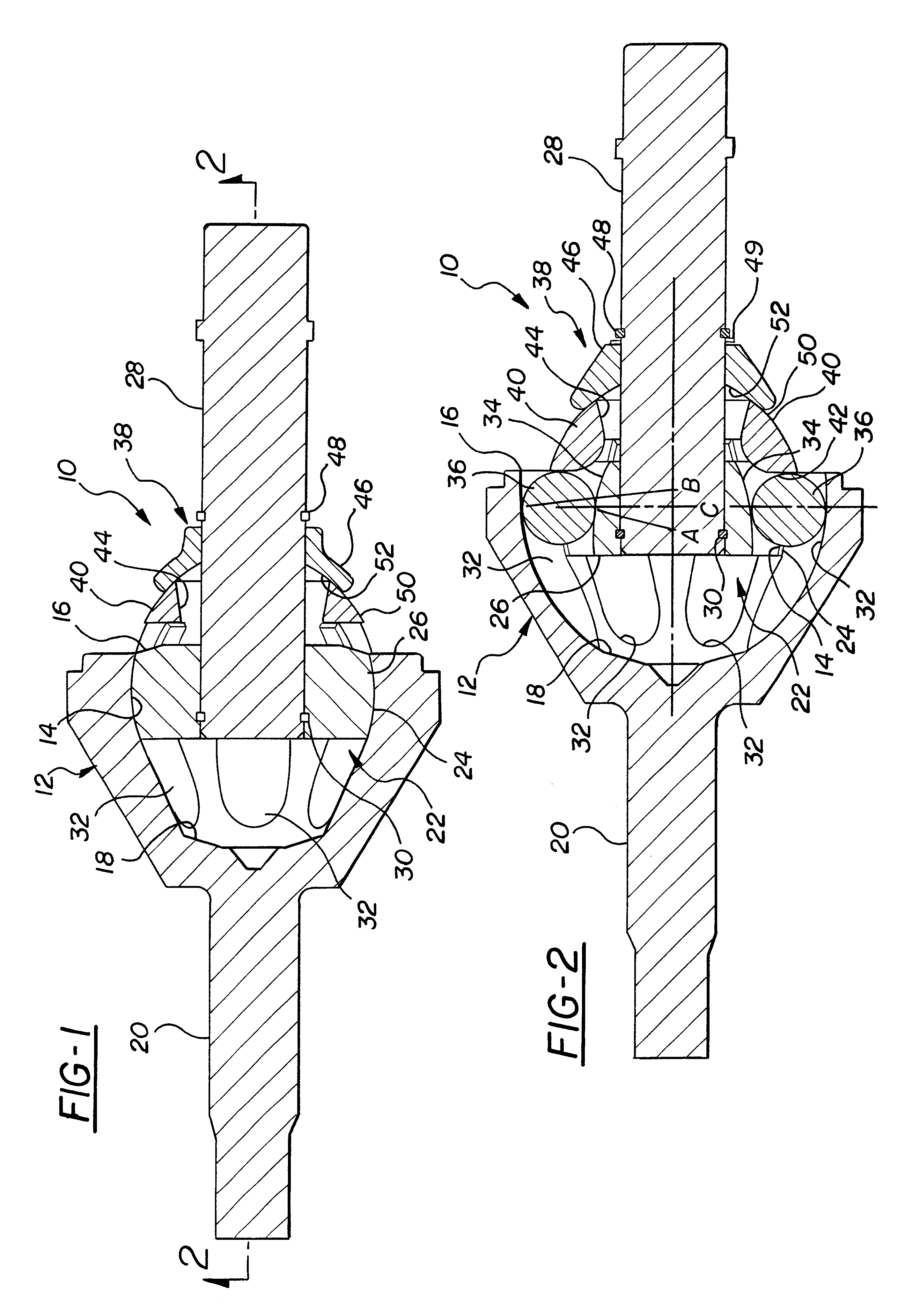
A constant velocity joint assembly constructed according to the invention is shown generally at 10 in FIGS. 1 and 2 and comprises an outer joint member or race 12 having an inner contact surface 14 which is preferably part-spherical. The outer joint member 12 has at least one open end 16 at one axial end of the joint. In the embodiment shown, the axially opposite end of the outer joint member 12 has a closed end 18 from which an axle 20 extends.
The joint assembly 10 includes an inner joint member generally indicated at 22 which is disposed at least partly within the outer joint member 12 and is formed with a part-spherical outer surface 24 that engages the complementing inner surface 14 of the outer joint member 12 to enable the outer 12 and inner 22 joint members to articulate about a common center C.
The inner joint member 22 includes an inner race portion 26 and an axle portion 28. The inner race portion 26 is disposed in contact with the outer joint member 12 and the axle portion...
second embodiment
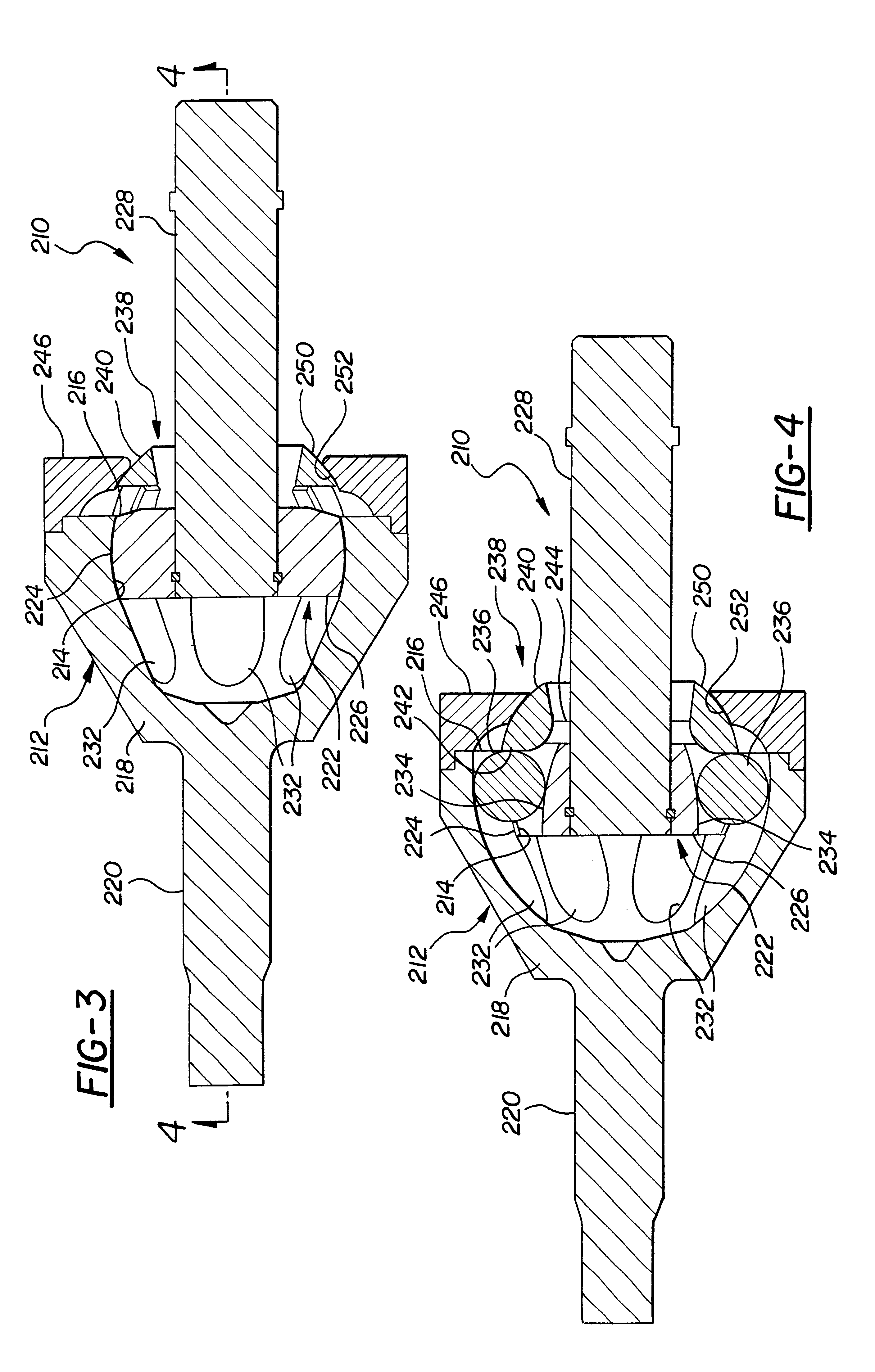
FIGS. 3 and 4 show an alternative embodiment of the invention, wherein the components and operation are identical except that the seat 46 is removed from the axle 28 and mounted on the outer joint member 12 as will be explained. For purposes of this second embodiment, the same reference numerals are used to designate like components, but are offset by 200.
The seat 246 of this alternative embodiment is in the form of an outer ring which is secured, either removably or permanently following installation of the inner joint member 22, to the outer joint member 12. The seat 246 has an inner surface 52 which engages the surface 50 of the partial cage 40 to provide articulated support to the partial cage 240 about the common center of the joint as before. The construction and method of assembly is otherwise identical, as is the operation of the joint. The seat 246 can be used in conjunction with the two piece or one piece inner joint member described above.
FIG. 6 shows an alternative embod...
PUM
 Abstract
Description
Claims
Application Information
 - R&D
- Intellectual Property
- Life Sciences
- Materials
- Tech Scout
- Unparalleled Data Quality
- Higher Quality Content
- 60% Fewer Hallucinations
Browse by: Latest US Patents, China's latest patents, Technical Efficacy Thesaurus, Application Domain, Technology Topic, Popular Technical Reports.
© 2025 PatSnap. All rights reserved.Legal|Privacy policy|Modern Slavery Act Transparency Statement|Sitemap|About US| Contact US: help@patsnap.com


