Method for producing a solid ceramic fuel cell

a fuel cell and ceramic technology, applied in the direction of cell components, final product manufacturing, sustainable manufacturing/processing, etc., can solve the problems of high electrolyte layer demands, high cost and complexity of evd process, and replace the expensive evd process with other coating systems, etc., to achieve high efficiency and low cost. , the effect of simple process

Inactive Publication Date: 2006-11-28
SIEMENS AG
View PDF14 Cites 19 Cited by
  • Summary
  • Abstract
  • Description
  • Claims
  • Application Information

AI Technical Summary

Benefits of technology

[0015]An embodiment of the invention is based on an object of providing an inexpensive and simple process for producing a solid oxide fuel cell with a high efficiency.

Problems solved by technology

Therefore, high demands are imposed on the electrolyte layer.
However, the EVD process is very expensive and complex.
The article deals with the problem of replacing the expensive EVD process with other coating systems.
One problem with the electrolyte layer is considered to reside in particular in the gastightness required.
A plasma coating process of this type throws up in particular two serious problems for the formation of a solid electrolyte layer: firstly, the molten material shrinks as it solidifies, so that a porosity which corresponds to the degree of shrinkage is formed in the solid electrolyte layer.
Therefore, a gastight layer cannot be achieved.
Secondly, a process of this type is scarcely able to achieve homogeneous formation of the solid electrolyte layer with a uniform thickness, since the individual tracks overlap at their boundary regions.
The fluctuations in thickness in the region of the solid electrolyte layer significantly reduce the efficiency of a fuel cell, since the ion conductivity across the solid electrolyte layer is adversely affected.
However, even with these known plasma-coating processes, it is impossible to achieve a high-quality solid electrolyte layer which has the quality of a solid electrolyte layer produced using the EVD process.

Method used


Image

  • Method for producing a solid ceramic fuel cell
  • Method for producing a solid ceramic fuel cell
  • Method for producing a solid ceramic fuel cell

Examples


Embodiment Construction

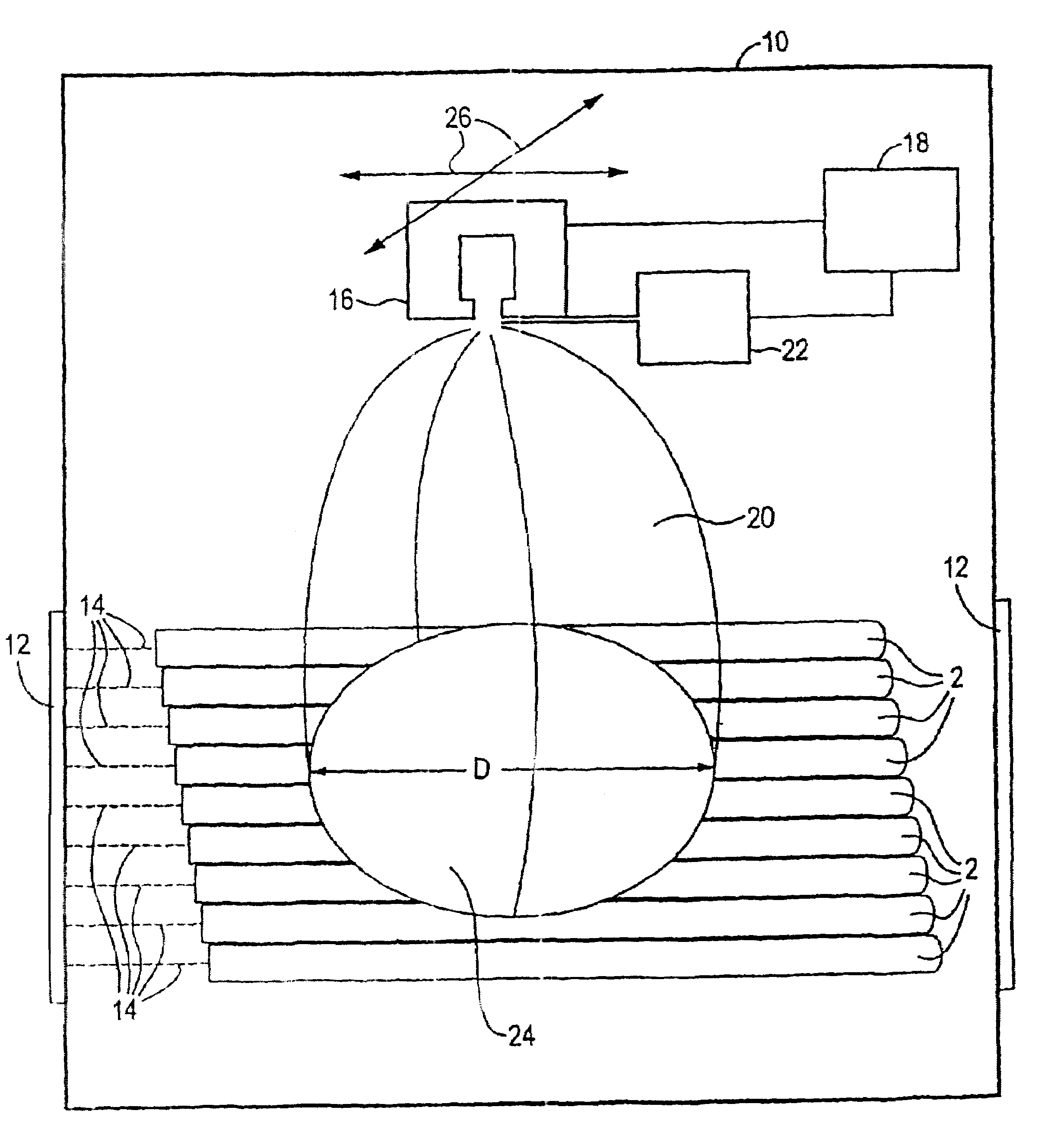
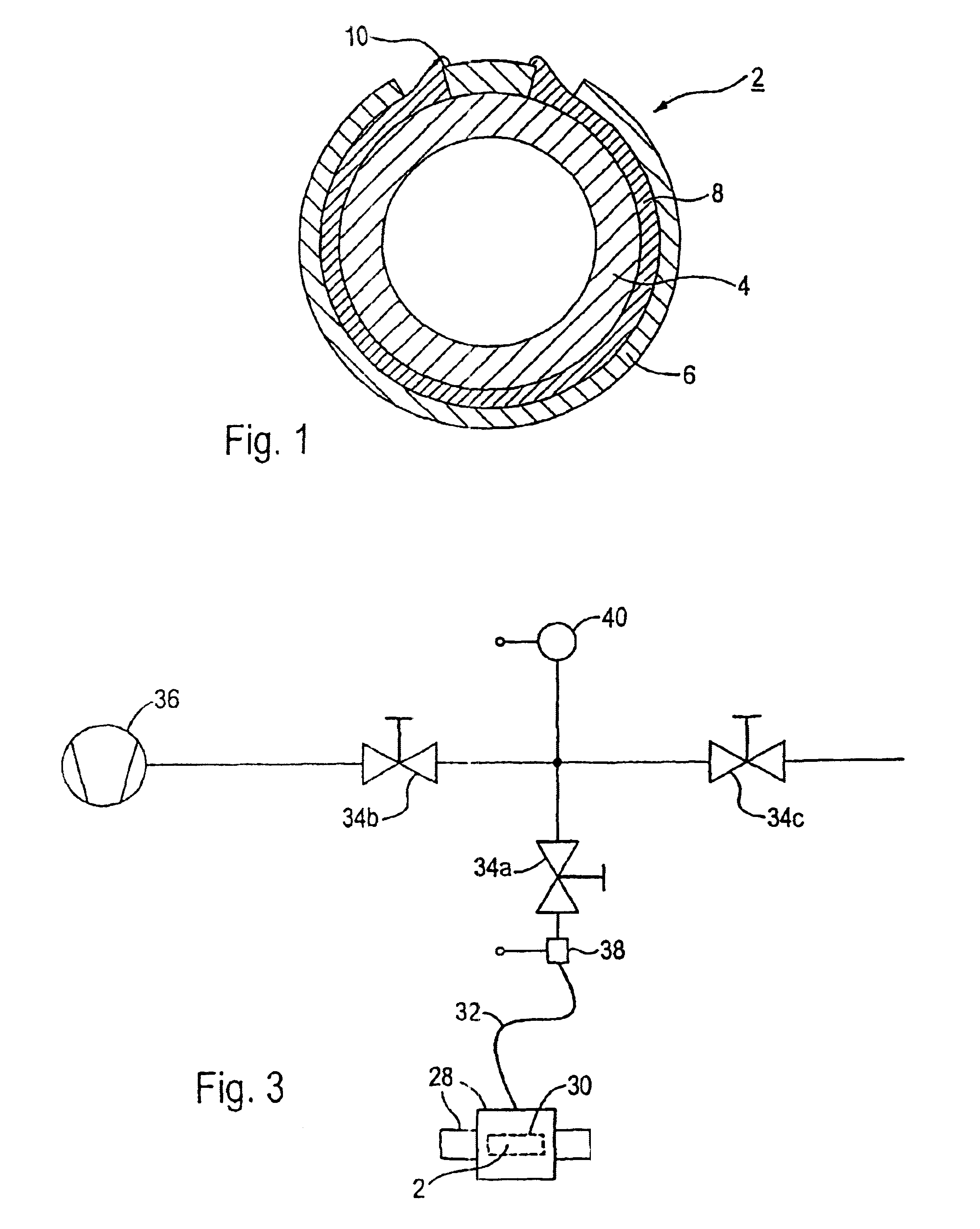
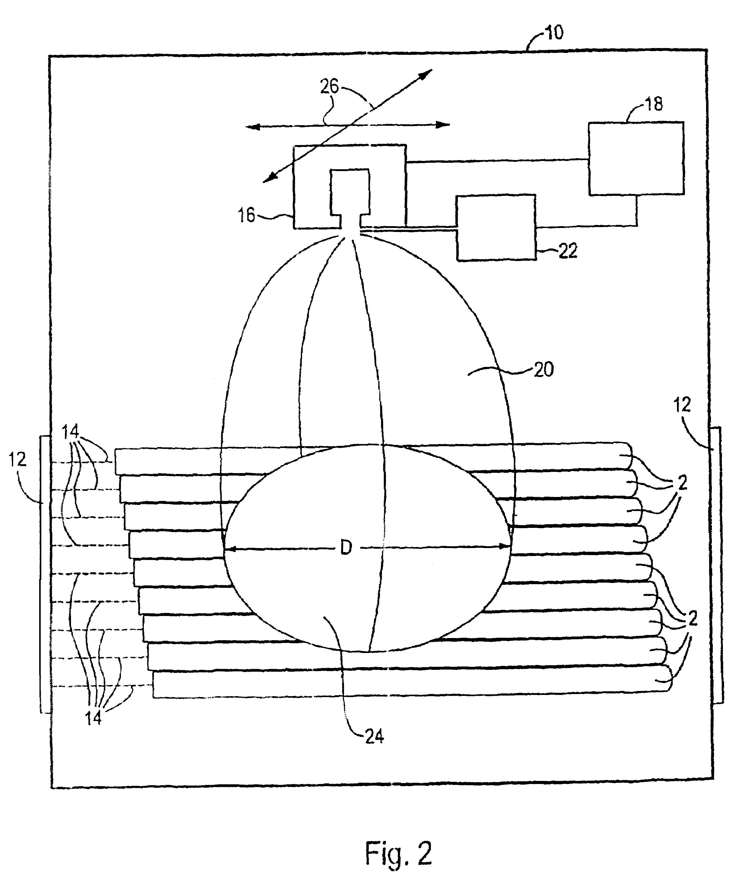
[0039]In accordance with FIG. 1, a solid oxide, tubular fuel cell 2 includes a first electrode, which is referred to as cathode 4, and a second electrode, which is referred to as anode 6. The cathode 4 and the anode 6 are designed as cylinders arranged concentrically with respect to one another and consist of a porous ceramic material. A fuel cell 2 of this type with solid oxide electrodes is also known as an “SOFC fuel cell” (solid oxide fuel cell). Air or oxygen is passed through the inner tubular cathode 4, while a fuel, for example hydrogen, is guided past the anode 6 surrounding the cathode 4. The cathode 4 is also known as the air electrode and the anode 6 as the fuel electrode. A solid electrolyte layer 8 is arranged between the cathode 4 and the anode 6.

[0040]On the one hand, the solid electrolyte layer 8 has to be gastight, in order to prevent contact between the air and the fuel via the porous electrodes 4, 6. At the same time, the solid electrolyte layer 8 has to have a g...


PUM

PropertyMeasurementUnit
pressureaaaaaaaaaa
thicknessaaaaaaaaaa
thicknessaaaaaaaaaa

Abstract

According to a method for producing a solid ceramic fuel cell, a solid electrolyte layer is gas-tightly deposited on an electrode inside a coating chamber, using a plasma spraying technique. The pressure inside the coating chamber is set at less than approximately 15 mbar for this purpose. A coating material is powder form, preferably with a particle diameter of significantly less than 10 μm, is finely dispersed in the plasma jet in such a way that the individual particles are isolated from each other when they meet the electrode. This enables a very homogenous and impervious solid electrolyte layer to be deposited.

Description

[0001]This application is the national phase under 35 U.S.C. § 371 of PCT International Application No. PCT / EP01 / 09760 which has an International filing date of Aug. 23, 2001, which designated the United States of America and which claims priority on European Patent Application number EP 00118769.9 filed Aug. 30, 2000, the entire contents of which are hereby incorporated herein by reference.FIELD OF THE INVENTION[0002]The invention generally relates to a process for producing a solid oxide fuel cell. Preferably, it relates to a process for producing one having a solid electrolyte layer arranged between two porous electrodes.BACKGROUND OF THE INVENTION[0003]A fuel cell generally comprises two electrodes, namely an anode and a cathode, between which an electrolyte layer is arranged. Oxygen is passed over the cathode surface and a fuel is passed over the anode surface. Ion exchange between the fuel and the oxygen takes place via the electrolyte layer, so that a voltage is formed betwee...

Claims


Application Information

Patent Timeline
Patent Type & Authority Patents(United States)
IPC IPC(8): B05D5/12H01M8/12C23C4/134H01M4/88H01M8/1213H01M8/124
CPCC23C4/127H01M8/1213H01M8/124H01M2008/1293Y02E60/521Y02E60/525C23C4/134Y02P70/50Y02E60/50
Inventor BARBEZAT, GERARDFLECK, ROBERTJANSING, THOMASLOCH, MICHAEL
Owner SIEMENS AG
Why Eureka
Try Eureka