Magnetic bearing control device

a control device and bearing technology, applied in mechanical energy handling, mechanical equipment, machines/engines, etc., can solve the problems of rotor rotation exceeding the maximum permissible rotation, centrifugal breakage, burning of windings,

Inactive Publication Date: 2003-09-09
KOYO SEIKO CO LTD
View PDF7 Cites 37 Cited by
  • Summary
  • Abstract
  • Description
  • Claims
  • Application Information

AI Technical Summary

Benefits of technology

In the magnetic beating control device as constituted above, when the motor drive circuit performs a switching operation of the switch portion to separate the inverter from the motor, when an over-speed detection signal is input from the over-speed detection circuit. Hence, irrespective of the states of the inverter for driving and controlling the motor and the inverter controller, the motor and the rotor can be securely stopped by shutting off the electric power from the inverter to the motor. Further, since the motor and the regenerative circuit can be connected by the switching operation, the rotor can be stopped promptly by employing a regenerative electric power of the motor that is supplied via the regenerative circuit to the magnetic bearing drive controller, as the magnetic bearing driving power.

Problems solved by technology

However, in the related magnetic bearing control device for TMP as described above, when the number of revolutions cannot be controlled due to a malfunction in the inverter or the DSP caused by the noise, for example, there is the fear that the rotor may be rotated beyond the maximum permissible rotation, causing a centrifugal breakage.
Further, there is the fear that an over-current may be supplied to the windings of the motor from the inverter, causing a burning of the windings or a thermal breakage due to rise in temperature of the inverter.
Also, when a malfunction such as an abnormal operation of the magnetic bearing or a power failure is detected, the DSP controls the inverter to brake the motor and stop the rotor promptly.
However, when the inverter itself get out of order and became uncontrollable, or the DSP break down and cannot control the inverter, the related magnetic bearing control device for TMP can not stop the rotational operation of the motor and the rotor, and prevent occurrence of the breakdown of the control object devices such as a centrifugal breakage of the rotor or a burning of the motor windings due to over-current, and the breakdown of the inverter within the control device.

Method used


Image

  • Magnetic bearing control device
  • Magnetic bearing control device

Examples


Embodiment Construction

The preferred embodiments of a magnetic bearing control device according to the present invention will be described below with reference to the accompanying drawings. In the following, a TMP magnetic bearing control device used in a Turbo Molecular Pump is exemplified.

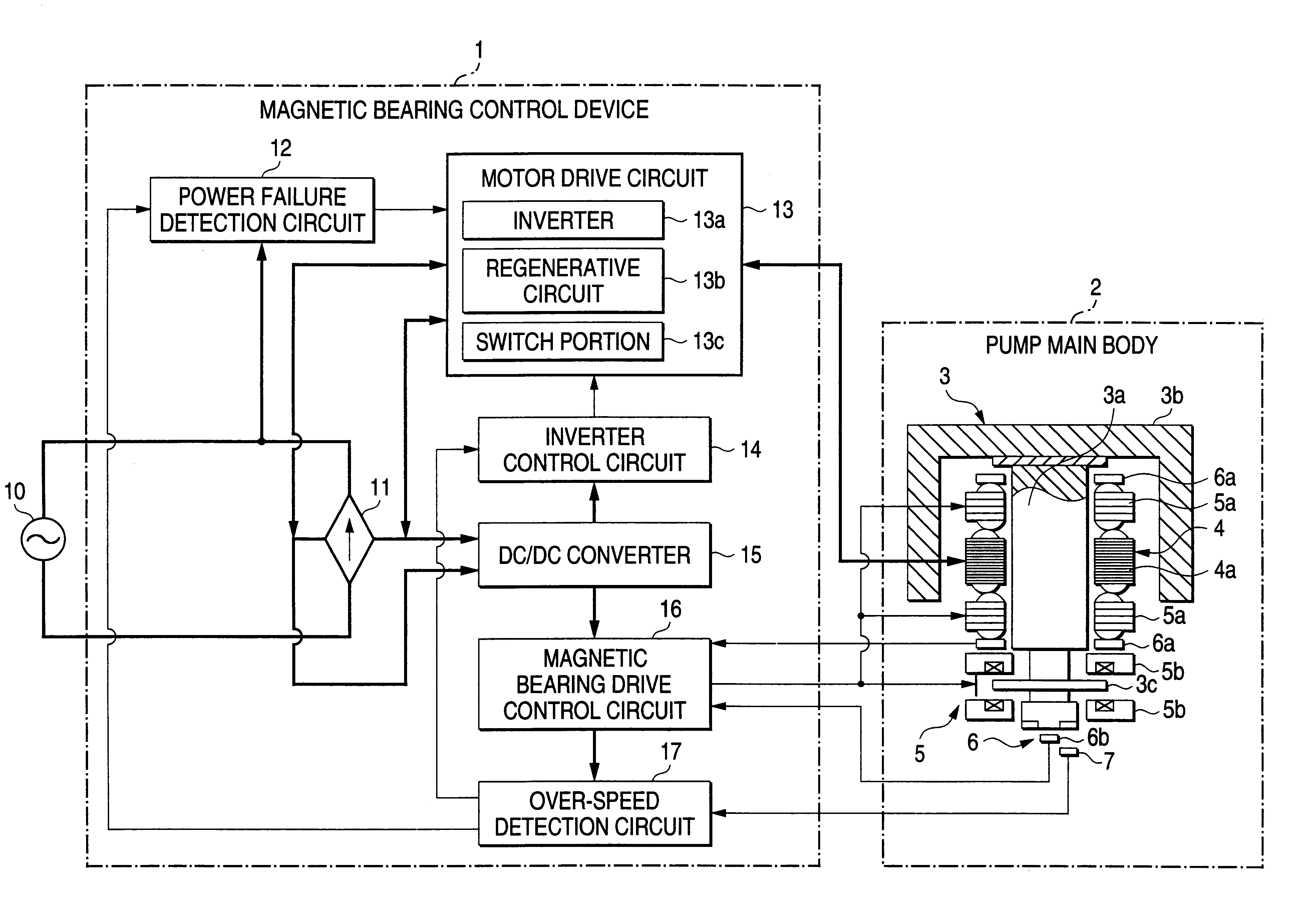
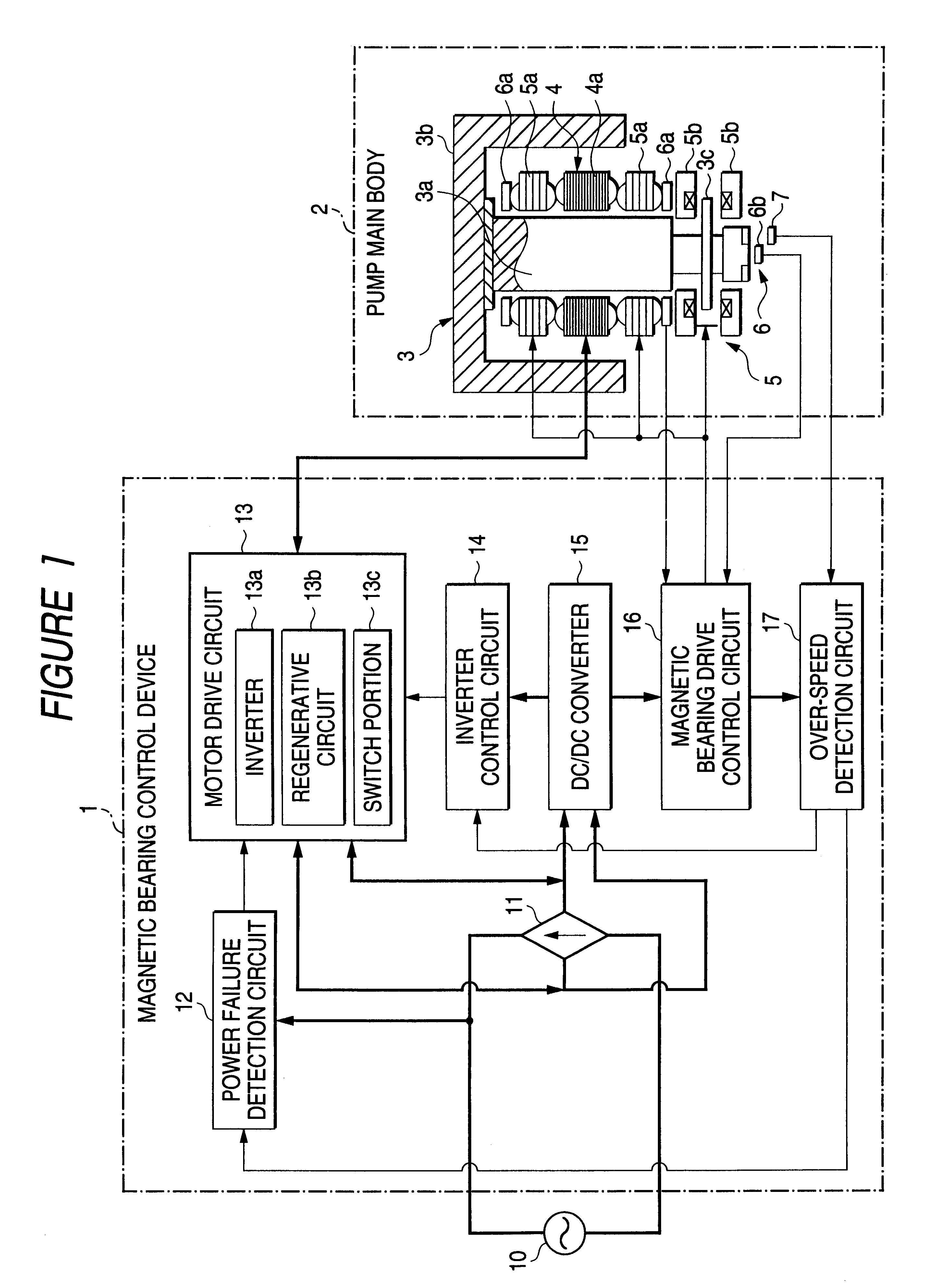
FIG. 1 is a block diagram showing the magnetic bearing control device according to one embodiment of the invention. In FIG. 1, the Turbo Molecular Pump has the magnetic bearing control device 1 of the invention and a pump main body 2, includes the magnetic bearing control device 1 and the pump main body 2 connected together via the cable or the communication line, for example. In the figure, the bold line indicates the power cable and the other line indicates the communication line for control signal.

The magnetic bearing control device 1 is provided with a rectifier circuit 11 connected to an AC power source 10 (e.g., 200V), a power failure detection circuit 12 for detecting the power failure of the AC power source 10,...


PUM


Abstract

The magnetic bearing control device (1) has a motor drive circuit (13) provided with an inverter (13a) for driving the motor (4) capable of generating an electric power, the inverter being controlled by an inverter control circuit (14), and an over-speed detection circuit (17) for detecting the number of revolutions of the rotor (3) that is being rotated by the motor (4), the rotor being supported in non-contact manner by a magnetic bearing (5). When the over-speed detection circuit (17) detects that the rotor (3) is being rotated at a preset number of revolutions or more, the motor drive circuit (13) performs a switching operation of a switch portion 13c provided in the motor drive circuit (13) to separate the inverter (13a) from the motor (4) and connect the motor (4) to a regenerative circuit (13b), whereby the magnetic bearing (5) is driven and controlled, employing a regenerative electric power of the motor (4).

Description

1. Technical Field of the InventionThe present invention relates to a magnetic bearing control device for controlling a magnetic bearing that supports a rotor effecting high speed rotation such as TMP (Turbo Molecular Pump) in non-contact manner in a state of magnetic levitation.2. Related ArtGenerally, a magnetic bearing for supporting a rotor in non-contact manner is known as a bearing for the rotor effecting high speed rotation. A device using such magnetic bearing is a Turbo Molecular Pump (hereinafter referred to as "TMP") used in the semiconductor manufacturing devices, for example. This Turbo Molecular Pump typically has a machine main body (pump main body) for supporting a rotation body (rotor) constituting a pump with a control type magnetic bearing in non-contact manner and rotating it with a motor, and a controller (magnetic bearing control device) for controlling the machine main body.In the related magnetic bearing control device for TMP, a DSP (Digital Signal Processor...

Claims


Application Information

Patent Timeline
Patent Type & Authority Patents(United States)
IPC IPC(8): F16C39/06F16C39/00F16C32/04
CPCF16C32/0444F16C2360/44F16C2360/45F16C2380/26F04D19/048F04D27/0292F16C32/0442F16C32/0451F16C32/0457
Inventor TANIGUCHI, MANABUMIYAGAWA, YASUKATA
Owner KOYO SEIKO CO LTD
Why Eureka
Try Eureka