Method and apparatus for locating the source of an unknown signal

a technology of unknown signals and methods, applied in direction finders, direction finders using radio waves, instruments, etc., can solve problems such as the inclination of satellite orbits in bandwidth limitations

Inactive Publication Date: 2003-09-09
KRATOS INTEGRAL HLDG LLC
View PDF4 Cites 74 Cited by
  • Summary
  • Abstract
  • Description
  • Claims
  • Application Information

AI Technical Summary

Problems solved by technology

It has bandwidth limitations for satellite orbits inclined to the Earth's equatorial plane, and needs two receivers which are on the same site and have common time and frequency references.
A

Method used


Image

  • Method and apparatus for locating the source of an unknown signal
  • Method and apparatus for locating the source of an unknown signal
  • Method and apparatus for locating the source of an unknown signal

Examples


Embodiment Construction

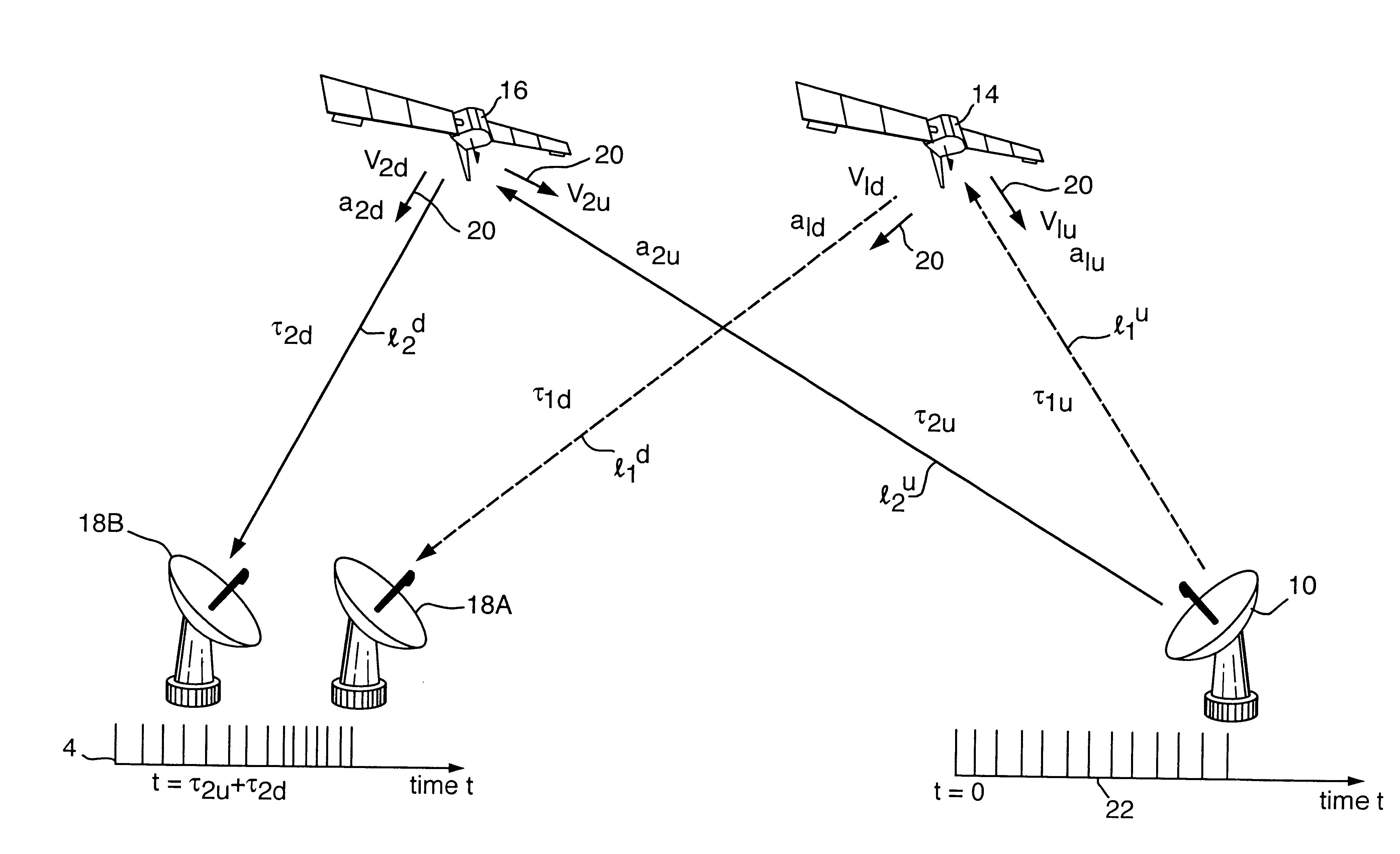
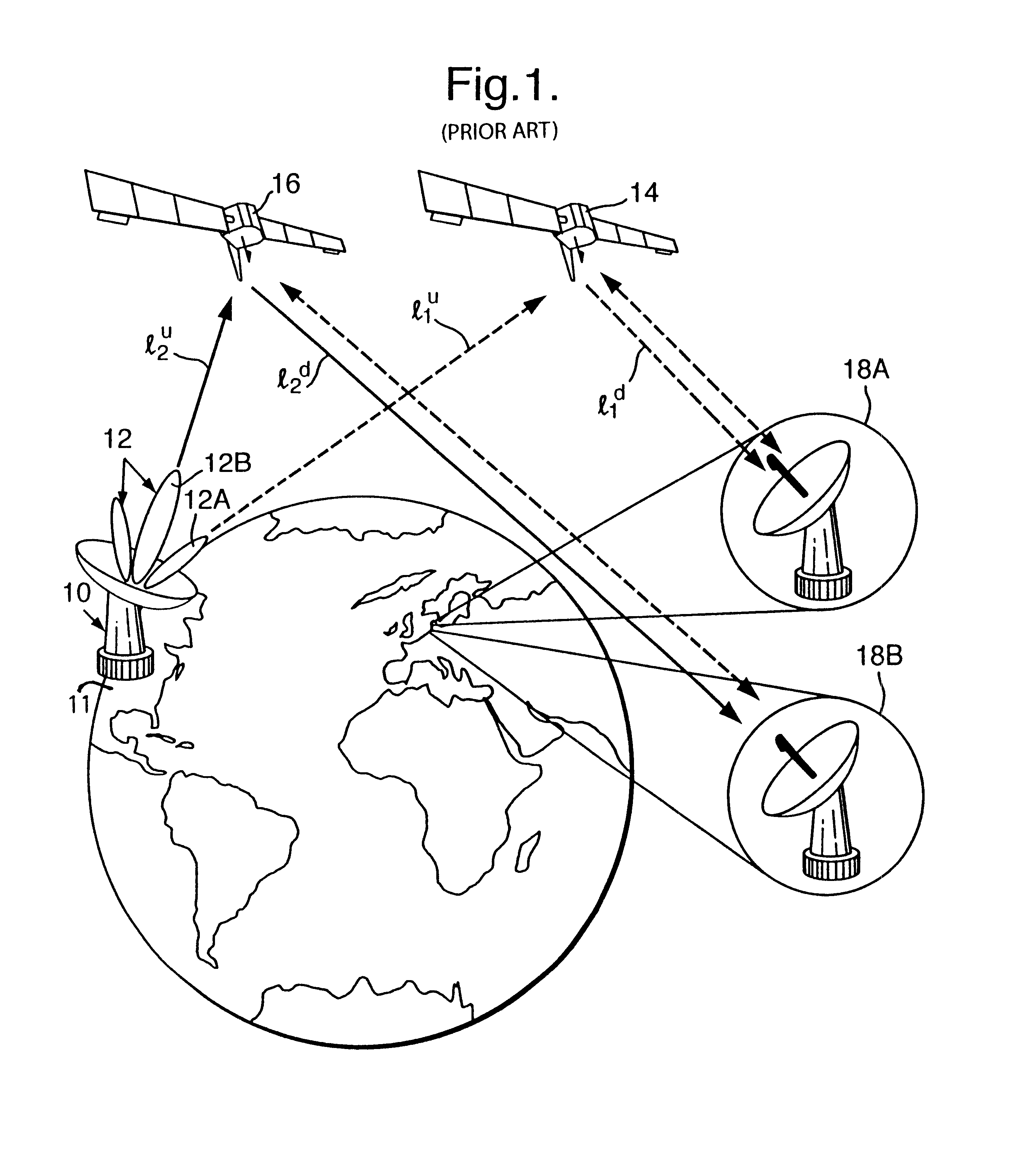
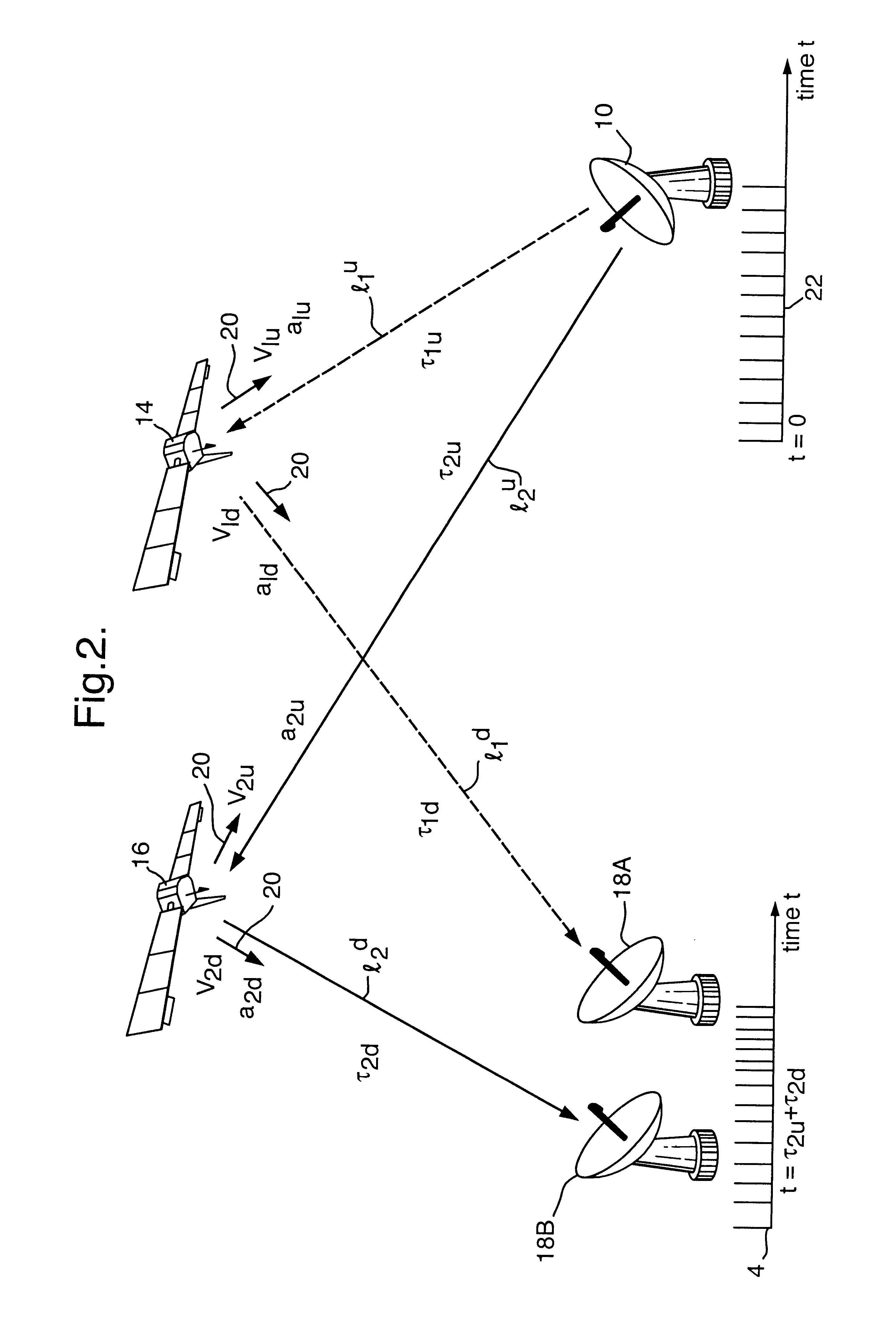
Referring to FIG. 1, an unknown transmitter 10 located in the United States of America 11 generates a signal which causes interference with satellite communications. The transmitter 10 has a radiation intensity pattern 12 with a sidelobe 12A directed to a first satellite 14 in a geostationary orbit, to which its signal propagates along a first uplink path l.sub.1.sup.u (dotted line). It also has a radiation pattern main lobe 12B directed to a second satellite 16 in such an orbit; its signal propagates along a second uplink path l.sub.2.sup.u to the satellite 16 and produces interference with communications signals using the latter. The unknown signal frequency is determined by spectrum analysis equipment which routinely monitors satellite channels. A typical communications satellite operating at Ku band (11-14 GHz) has 16 channels each 36 MHz wide and each capable of carrying 100 communications signals. The superscript "u" to path references l.sub.1.sup.u and l.sup.2.sup.u denotes u...


PUM


Abstract

A method of determining the location of an unknown source 10 transmitting a signal to satellite relays 14 and 16 comprises receiving replicas of the signal from the relays at receivers 18. The receivers 18 also transmit and receive reference signals via respective relays 14 and 16. All signals are downconverted, digitized and correlated with one another in pairs using a correlation function including a term which compensates for time varying differential frequency offset (DFO). Compensation for time varying differential time offset or time dilation is achieved by replicating or adding to signal samples and applying phase corrections. This procedure enables a correlation maximum and associated measurement results to be obtained despite the effects of relay satellite motion which mitigate against this. Results are used in a prior art geometrical technique to locate the unknown transmitter.

Description

1. Field of the InventionThis invention relates to a method and apparatus for locating the source of an unknown signal received by a plurality of signal relays.2. Discussion of Prior ArtIn IEEE Trans. on Aerospace and Electronic Systems, Vol. AES-18, No. 2, March 1982, P C Chestnut describes the basic technique of locating the source of an unknown signal such as a ground-based communications antenna; it involves determining the time difference of arrival (TDOA) and / or frequency difference of arrival (FDOA) of two signals from the source relayed to receivers by respective intercept platforms in the form of relay satellites in geostationary or geosynchronous orbits. The signals are relayed by the satellites along two independent signal paths to a receiving station, ie ground-satellite-ground paths. One satellite lies in the main beam or lobe of the source antenna radiation pattern and the other in a sidelobe. Each satellite accepts a signal (uplink) from the source, frequency shifts i...

Claims


Application Information

Patent Timeline
IPC IPC(8): G01S1/00G01S1/04G01S5/02G01S5/00G01S1/02G01S5/06G01S19/21G01S19/26
CPCG01S1/045G01S5/0009G01S5/02G01S1/026G01S5/06G01S5/0246G01S19/10
Inventor GRIFFIN, CHRISTOPHEREDMONDS, PAUL R.DUCK, SIMON R.
Owner KRATOS INTEGRAL HLDG LLC
Why Eureka
Try Eureka