Linear control loading system

a loading system and flight simulator technology, applied in the field of flight simulator control and flight simulator control, can solve the problems of low cost system, less sophisticated low cost system, and difficult to efficiently and realistically simulate flight characteristics

Inactive Publication Date: 2003-09-16
AVIATION SIMULATION TRAINERS +1
View PDF9 Cites 17 Cited by
  • Summary
  • Abstract
  • Description
  • Claims
  • Application Information

AI Technical Summary

Benefits of technology

The shaft runs through the springs and the actuators. The shaft is rotatably secured to each fixed actuator and threaded within each adjustable actuator. As the shaft is rotated in an increase direction, each adjustable actuator slides toward the respective fixed actuator, thereby compressing the springs and increasing control load. As the shaft is rotated in a decrease direction, each adjustable actuator slides away from the respective fixed actuator, thereby relieving compression on the springs and decreasing control load. The increase direction and the decrease direction are determined by the threads on the shaft and each adjustable actuator.
In use, the computer monitors factors such as airspeed and orientation of the aircraft being simulated and determines an appropriate control load level. When the computer determines that control load should be increased it causes the motor to rotate the shaft in the increase direction, thereby compressing the springs and increasing the force needed to move the control. Alternatively, when the computer determines that control load should be decreased it causes the motor to rotate the shaft in the decrease direction, thereby relieving compression on the springs and decreasing the force needed to move the control. As a pilot manipulates the control, he or she experiences more or less control load, just as in a real aircraft.

Problems solved by technology

This flight characteristic has proven difficult to efficiently, and realistically simulate, as part of a flight simulator.
Current systems fall into one of two categories, complicated and sophisticated high cost systems and less sophisticated low cost systems.
High cost systems typically use hydraulics with a closed loop control scheme to simulate control load forces.
These systems are complex, typically have many moving parts, and are subject to high maintenance requirements.
Complexity, cost, and maintenance requirements prevent these systems from being used in all but the most expensive flight simulators.
These systems are simple but not realistic.
These systems typically have no way to adjust the force according to airspeed or other factors.
Since they cannot realistically simulate control load, these systems can only be used in very rudimentary flight simulators.
When the computer determines that control load should be increased it causes the motor to rotate the shaft in the increase direction, thereby compressing the springs and increasing the force needed to move the control.

Method used


Image

  • Linear control loading system
  • Linear control loading system
  • Linear control loading system

Examples


Embodiment Construction

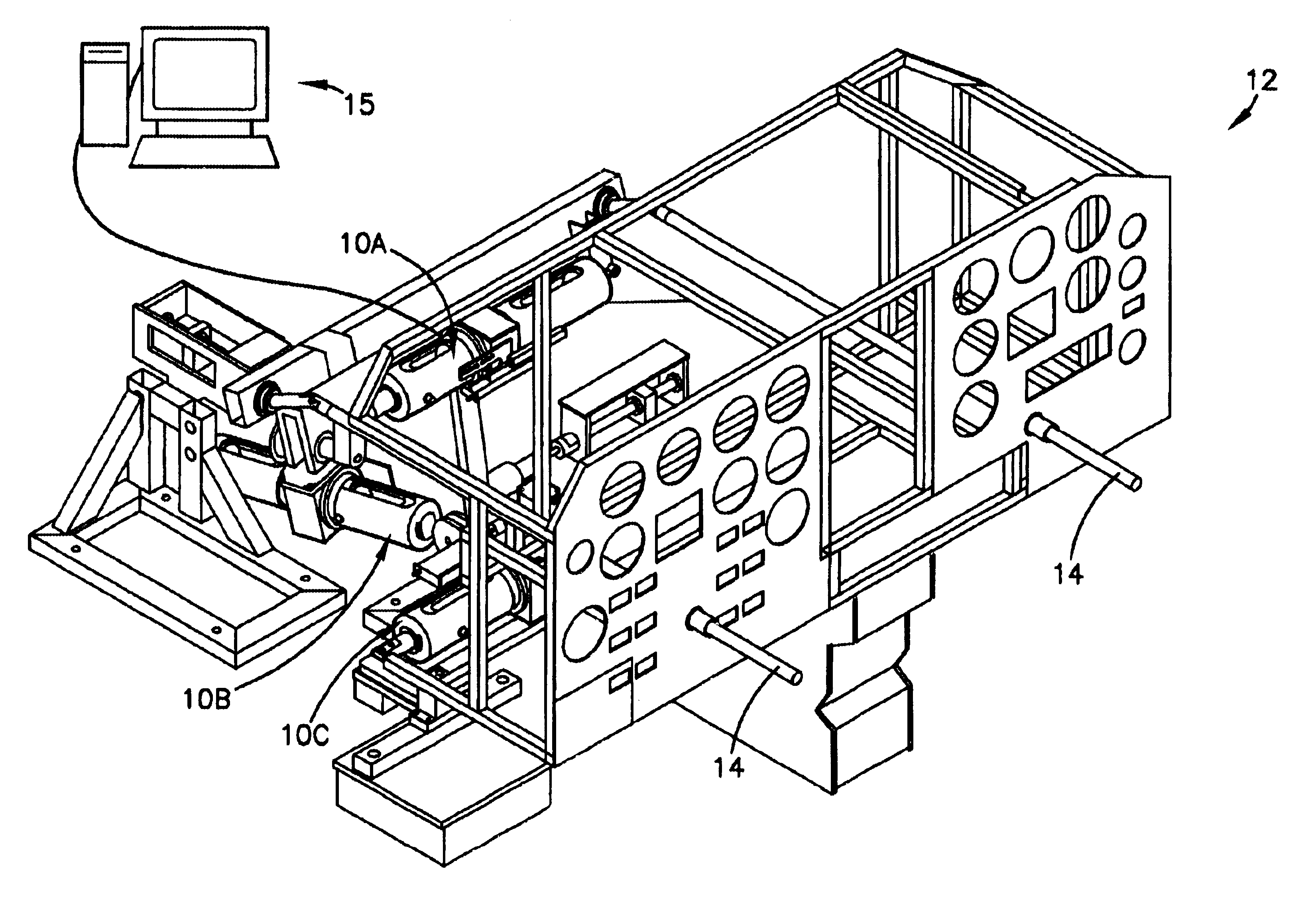
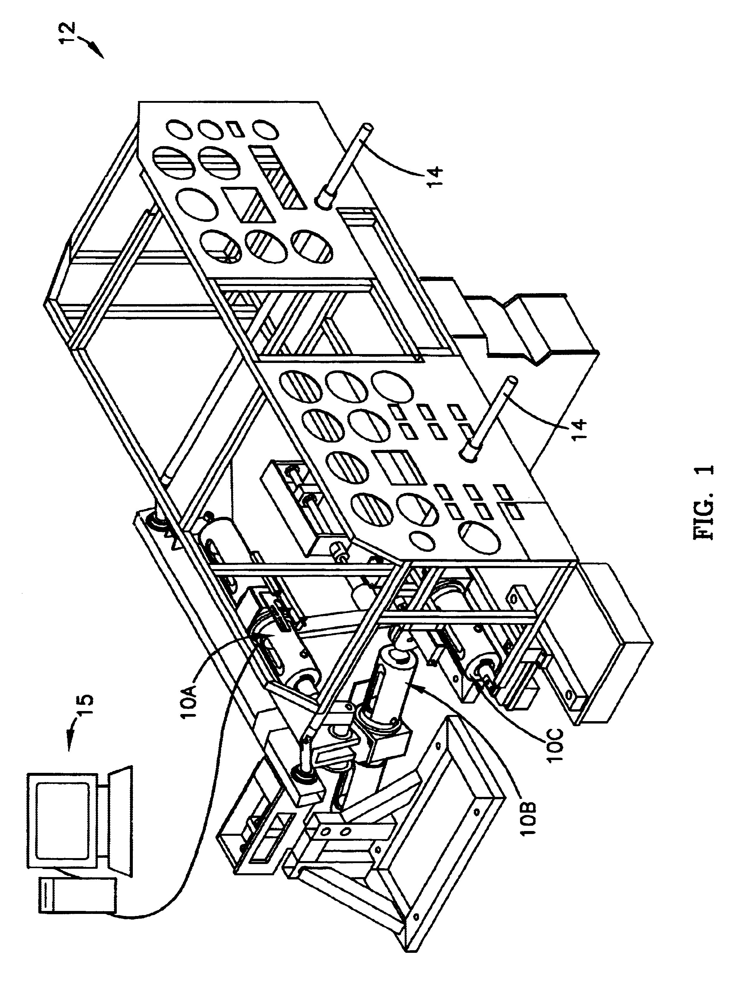
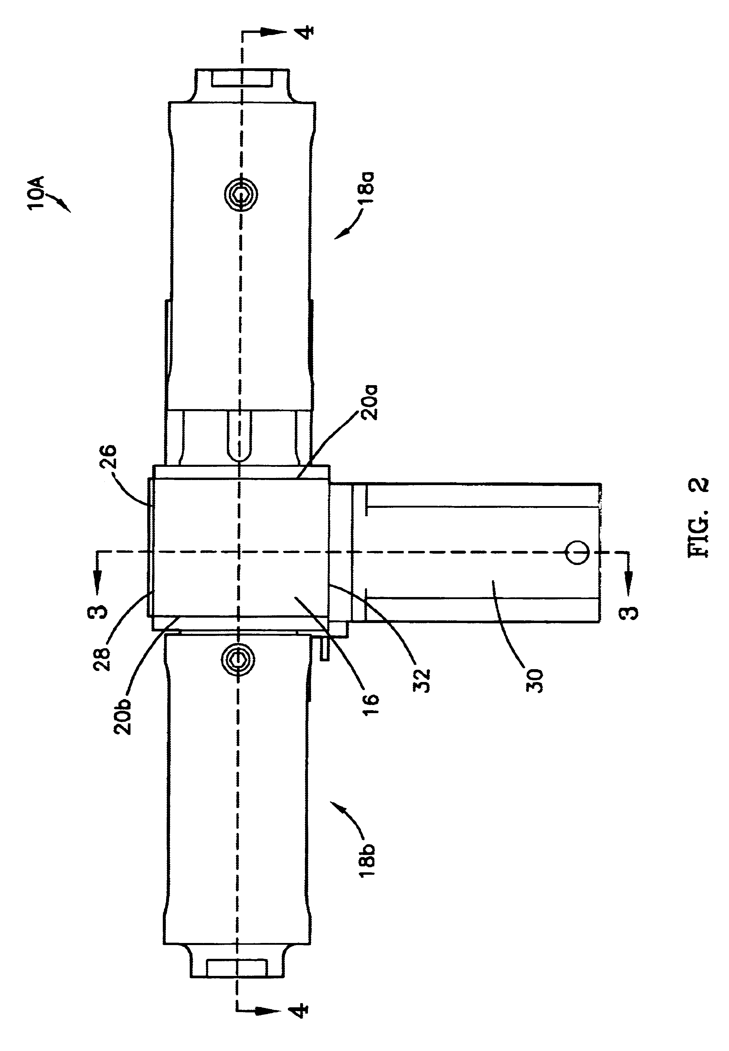
FIG. 1 illustrates several linear flight simulator control loading systems 10A, 10B, 10C in accordance with a preferred embodiment of the present invention and shown in the preferred environment of use as part of a flight simulator 12. The simulator 12 is operable to simulate several flight characteristics of one or more aircraft in order to allow a pilot to practice flying the aircraft. The simulator includes one or more controls 14 such as a yoke and rudder pedals that allow the pilot to interact with a computer 15, and the loading systems 10A, 10B, 10C.

The computer 15 monitors each control's 14 position and commands the flight simulator 12 in order to interpret the pilot's actions and accurately simulate flight. The computer 15 is capable of storing and executing software and may be a commonly available personal computer, such as those available from Compaq Corporation or may be a micro-computer, such as those available from International Business Machines. Based upon the pilot m...


PUM


Abstract

A flight simulator control loading system (10A) comprises a compression assembly (18a), a tension assembly (18b), and a motor (30) which rotates a shaft (78). The compression assembly (18a) and the tension assembly (18b) each include a fixed actuator (50a,50b) fixedly secured to an outer housing (46a,46b), and an adjustable actuator (52a,52b) slidably mounted within a guide housing (48a,48b). Springs (54a,54b,56a,56b) are located between and push against the actuators (50a,50b,52a,52b). As the shaft (78) is rotated in an increase direction, each adjustable actuator (52a,52b) slides toward the respective fixed actuator (50a,50b), compressing the springs (54a,54b,56a,56b) and increasing control load. As the shaft (78) is rotated in a decrease direction, each adjustable actuator (52a,52b) slides away from the respective fixed actuator (50a,50b), relieving compression on the springs (54a,54b,56a< / HI

Description

1. Field of the InventionThe present invention relates to flight simulators and flight simulator controls. More particularly, the present invention relates to a linear flight simulator control loading system that linearly adjusts a control load to more realistically simulate an aircraft in flight.2. Description of Prior ArtMany aircraft use mechanical linkages to connect a control to one or more control surfaces. The control may be a yoke or rudder pedals and allow a pilot to manipulate the control surfaces, such as, ailerons, elevators, and rudders. An aileron is typically mounted on a wing of an aircraft and is used to control roll of the aircraft. An elevator is typically mounted on a tail section of an aircraft and is used to control pitch of the aircraft. A rudder is typically mounted on a tail section of an aircraft and is used to control yaw of the aircraft.These control surfaces function by deflecting airflowing past them. For instance, as air flows past a wing, an aileron c...

Claims


Application Information

Patent Timeline
Patent Type & Authority Patents(United States)
IPC IPC(8): G09B9/10G09B9/02
CPCG09B9/10
Inventor HORN, DAVID
Owner AVIATION SIMULATION TRAINERS
Why Eureka
Try Eureka