Micro liquid evaporator

a liquid evaporator and micro-evaporator technology, applied in the direction of evaporator regulation/control, separation process, laboratory glassware, etc., can solve the problems of substantial measurement errors, affecting the accuracy of nvr measurement, and affecting the safety of process workers, so as to reduce the amount of hazardous materials and accurate measurement of nvr

Inactive Publication Date: 2003-09-16
ERA SYSTEMS CORPORATION
View PDF29 Cites 35 Cited by
  • Summary
  • Abstract
  • Description
  • Claims
  • Application Information

AI Technical Summary

Benefits of technology

Among the advantages of the invention is the controlled evaporation of a liquid, such as a solution, on a drop-by-drop basis. Another advantage of the invention is the accurate measurement of NVR, particularly at concentrations of less than 3 mg / L. A further advantage of the invention is the reduction in the amount of hazardous material released into the environment as a result of the evaporation of the liquid or solvent.

Problems solved by technology

Current methods for the deposition and measurement of solvent non-volatile residue (NVR), however, suffer from a variety of problems.
This method has many inherent errors and problems that may result in substantial errors in measurement, particularly at concentration levels (solute / solvent) of less than 3 mg / L or its equivalent.
One additional problem associated with boiloff evaporation and release of the vapor to the atmosphere is that the process may be hazardous to the environment and to laboratory workers.

Method used


Image

  • Micro liquid evaporator
  • Micro liquid evaporator
  • Micro liquid evaporator

Examples


Embodiment Construction

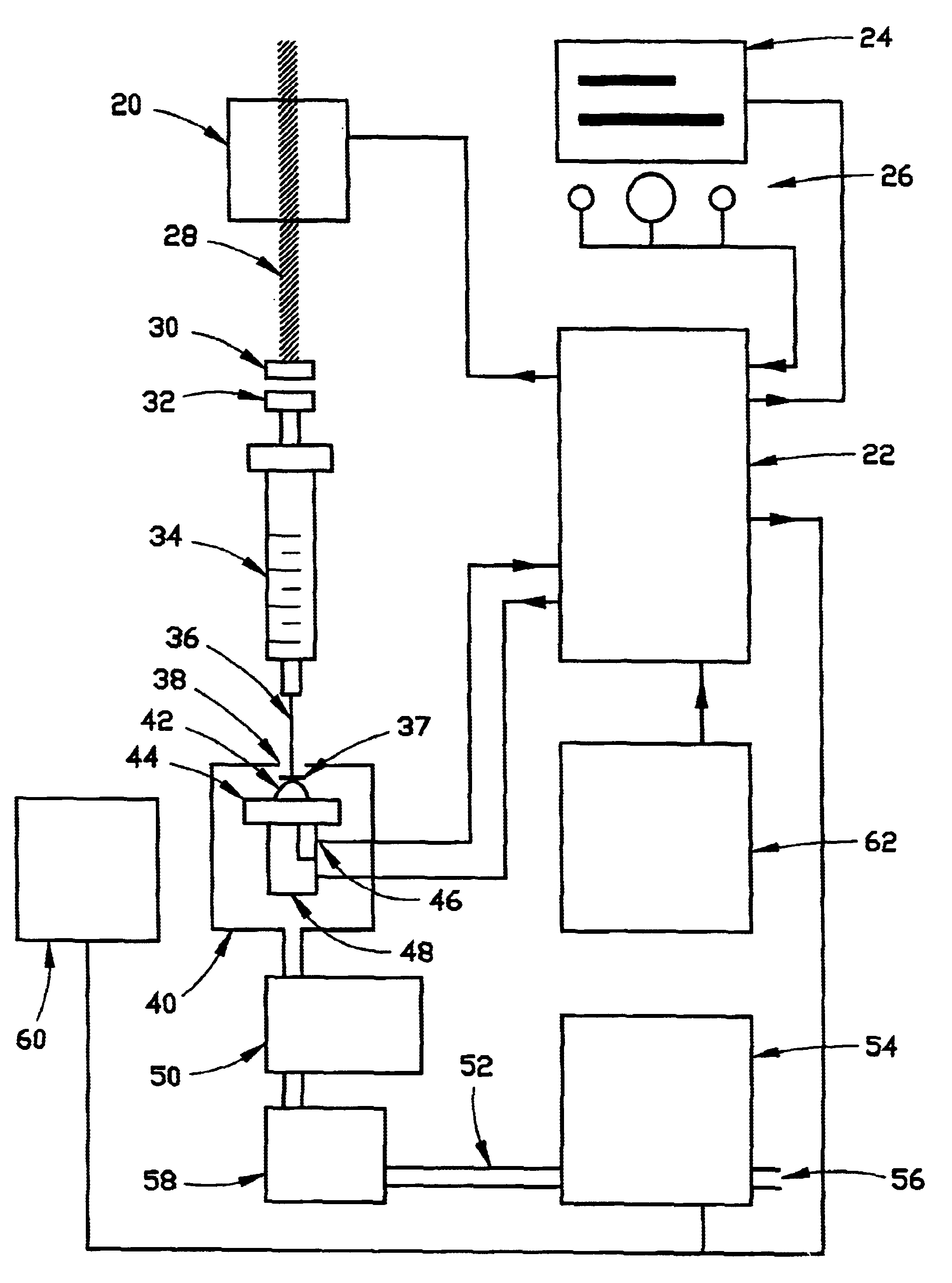
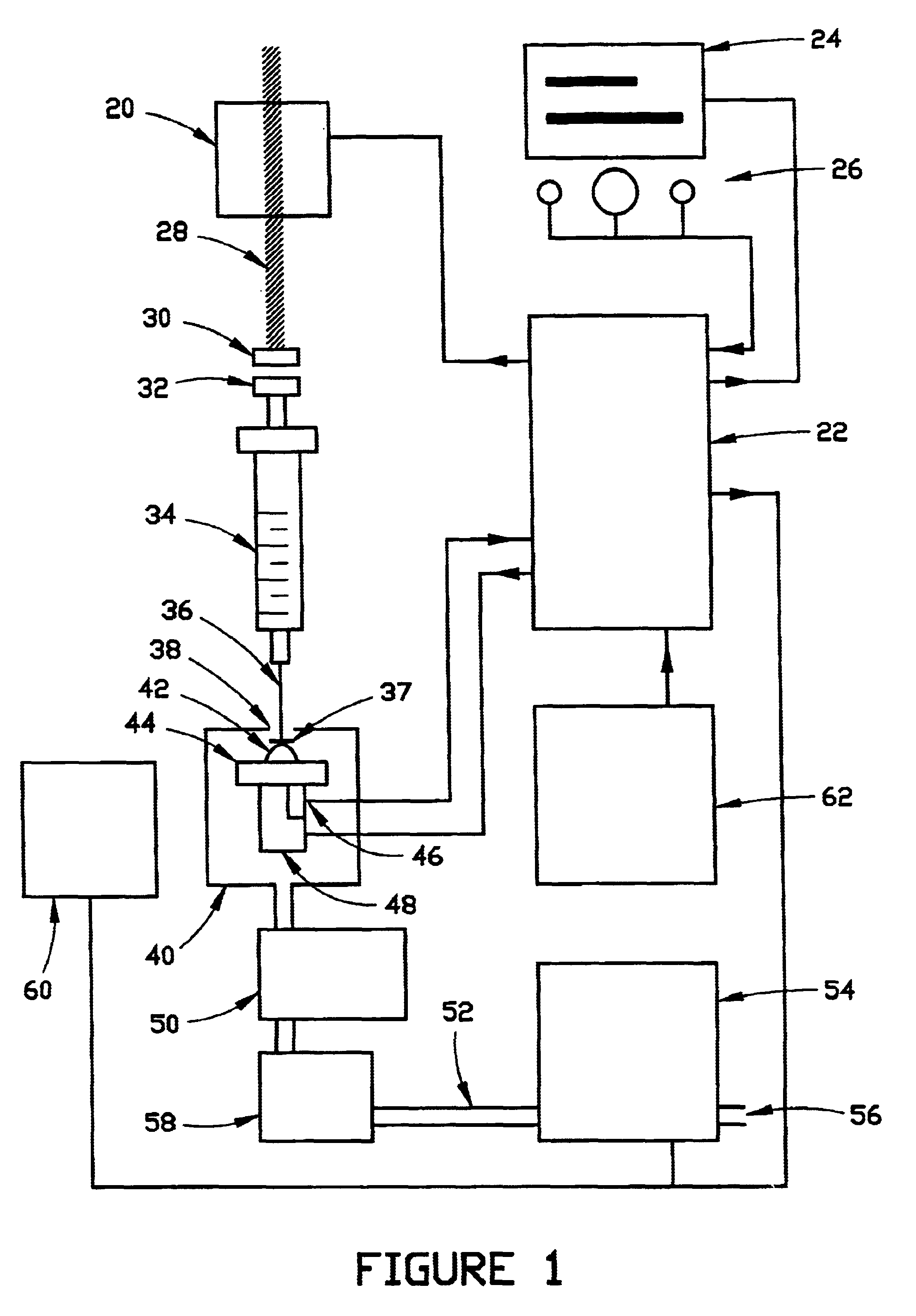
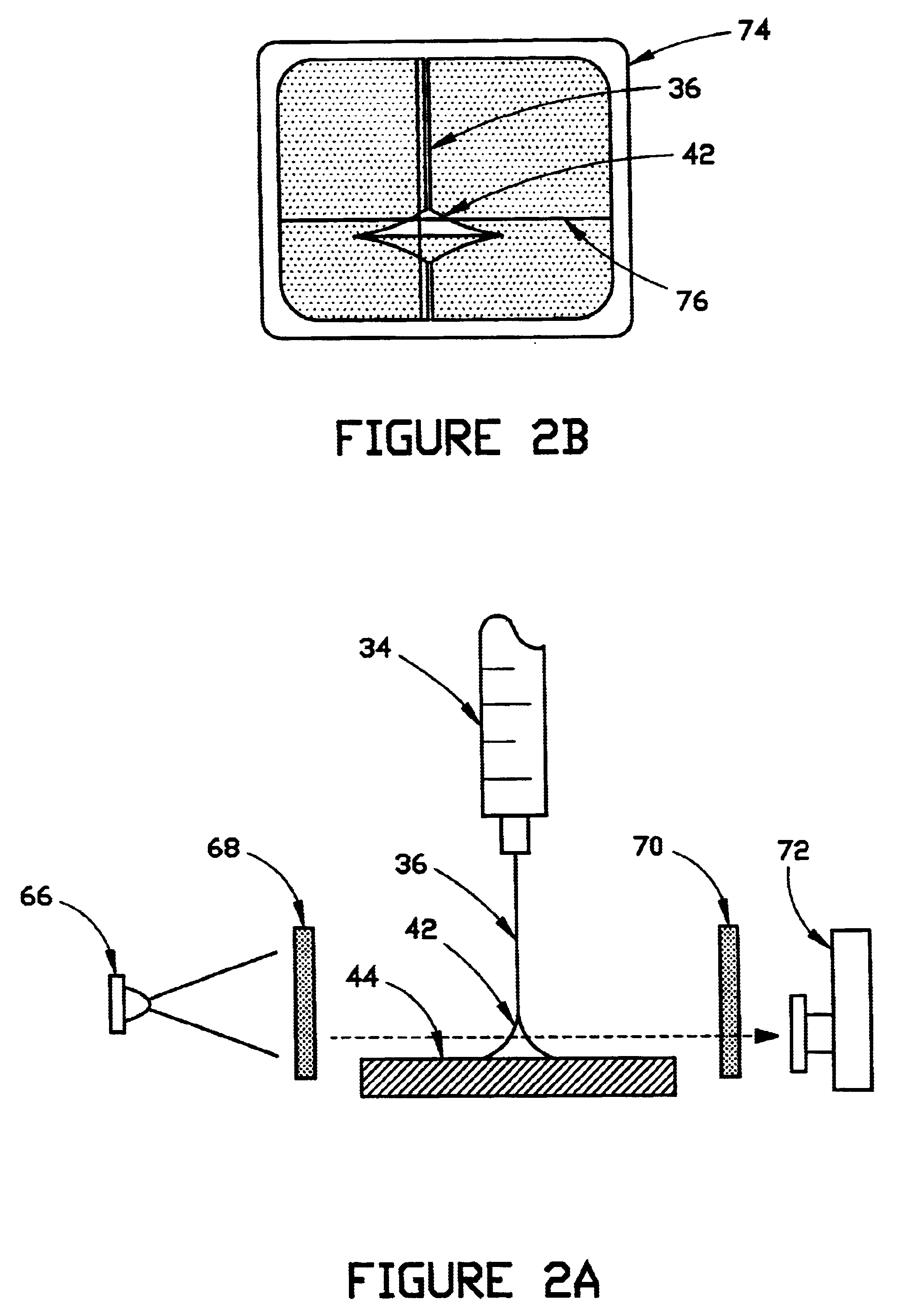
The overall design of the micro-liquid evaporator is shown in FIG. 1 with block representations of certain components, the nature of which would be known to those having ordinary skill in the art to which the invention relates. Six of the preferred liquid or solvent-loss detection means are shown in FIGS. 2 through 7. Obviously, the means of detecting the evaporation of the liquid or solvent droplet may be any practical method, as shown or other than those shown, that performs the process of measuring the loss of liquid or solvent during the evaporative process. Two views of a testing enclosure are shown in FIGS. 8 and 9. Other enclosure arrangements providing similar effects may also be used. The inventions hereinafter described and claimed are the unique combinations of the several parts of the apparatus that permit the automated, controlled evaporative process to occur.

The overall detail and logical arrangements of a preferred embodiment of the invention are illustrated in FIG. 1...


PUM

PropertyMeasurementUnit
internal diameteraaaaaaaaaa
concentrationaaaaaaaaaa
concentrationsaaaaaaaaaa

Abstract

The drop-by-drop evaporation of a liquid or solution is controlled by monitoring the disappearance of each successive droplet and by actuating the deposition of the next droplet until the desired volume is deposited. In the case of a solution, non-volatile residue (NVR) is collected on a deposition surface plate as a relatively small mound. One of a variety of methods may be employed to measure the evaporative behavior of each droplet and to key the deposition procedure. The process is preferably carried out employing a clean deposition surface plate that is maintained at or below the boiling point of the particular liquid or solvent being deposited. The environment is preferably controlled so that inadvertent contamination is precluded from interfering, and thus the method permits the automatic, micro-processor controlled evaporation of liquids with the resultant deposition of non-volatile residues from solutions within relatively short periods of time. The deposited residue may then be quantified at levels down to and below about 1 ug/mL (1 mg/L) by one of several means for determining the amount of non-volatile residue remaining.

Description

This invention generally relates to an apparatus and method for the controlled evaporation of liquids, including solutions. More particularly, the preferred embodiment of this invention comprises an improved apparatus and method for evaporating the solvent of a solution on a drop-by-drop basis. A preferred embodiment of the invention also provides means for measuring the amount of the solute remaining after the solvent has substantially evaporated.BACKGROUND AND DESCRIPTION OF THE PRIOR ARTIt is known that the amount of solute contained in a quantity of solution may be measured by a variety of means after the solvent of the solution has evaporated. Current methods for the deposition and measurement of solvent non-volatile residue (NVR), however, suffer from a variety of problems.The most common method involves removing the solvent and thereby concentrating the residue by atmospheric evaporation of 100 to 1000 mL of liquid solvent followed by weighing the residue. This method has man...

Claims


Application Information

Patent Timeline
Patent Type & Authority Patents(United States)
IPC IPC(8): B01D1/16B01D1/00G01N1/40G01N21/17G01N21/47
CPCB01D1/0082B01D1/16G01N1/40G01N21/17Y10T436/119163G01N2001/4027Y10T436/12Y10T436/112499Y10T436/2575G01N21/47
Inventor ANDERSON, JOHN LYNDERUSSELL, ROSS F.HANON, DAVID O.EDWARDS, JAMES NELSON
Owner ERA SYSTEMS CORPORATION
Why Eureka
Try Eureka