
Multiband antenna

a multi-band antenna and antenna support technology, applied in the direction of resonant antennas, antenna supports/mountings, radiating element structural forms, etc., can solve the problem of not yet completing the process of harmonics

Inactive Publication Date: 2003-09-16
NOKIA CORP
View PDF10 Cites 19 Cited by
  • Summary
  • Abstract
  • Description
  • Claims
  • Application Information

AI Technical Summary

Benefits of technology

The present invention provides a multiband antenna that is compact.
Preferably, said further element is slotted such that said further element has a quarter wave resonance mode at a third frequency and the further element has 3 / 4 wave resonance mode at a fourth frequency or its slot has a quarter wave resonance mode at a fourth frequency, the fourth frequency not being substantially three time the third frequency, More preferably, the first and third frequencies are sufficiently close to provide a single unbroken usable bandwidth and / or the second and fourth frequencies are sufficiently close to provide a single unbroken usable bandwidth. This gives a broader bandwidth.

Problems solved by technology

However, this harmonization has not yet been completed.
Additionally, national spectrum management authorities do not necessarily decide to allocate the same bands to the public land mobile network service.

Method used


Image

  • Multiband antenna
  • Multiband antenna
  • Multiband antenna

Examples


Embodiment Construction

Embodiments of the present invention will now be described, by way of example, with reference to the accompanying drawings.

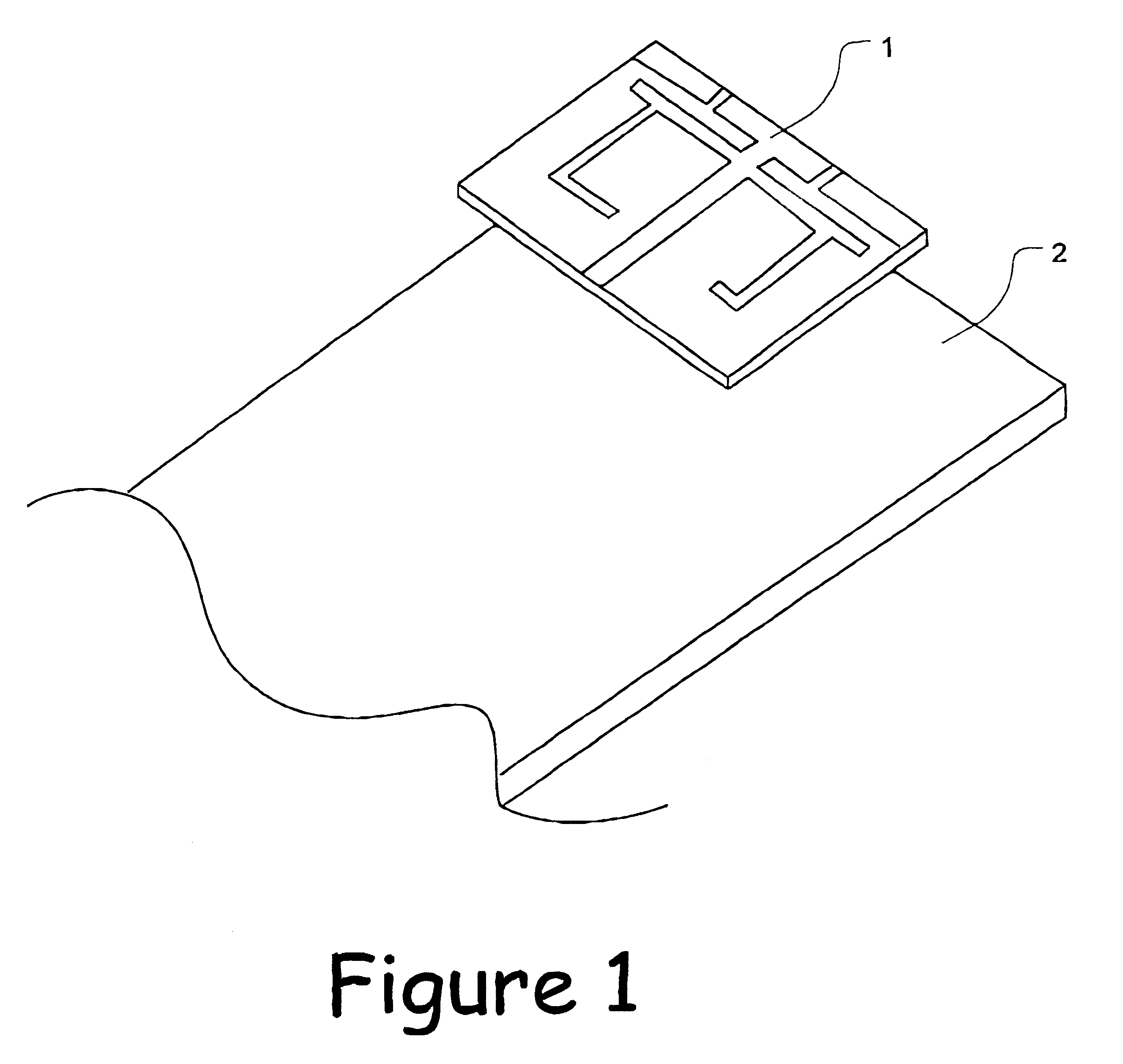
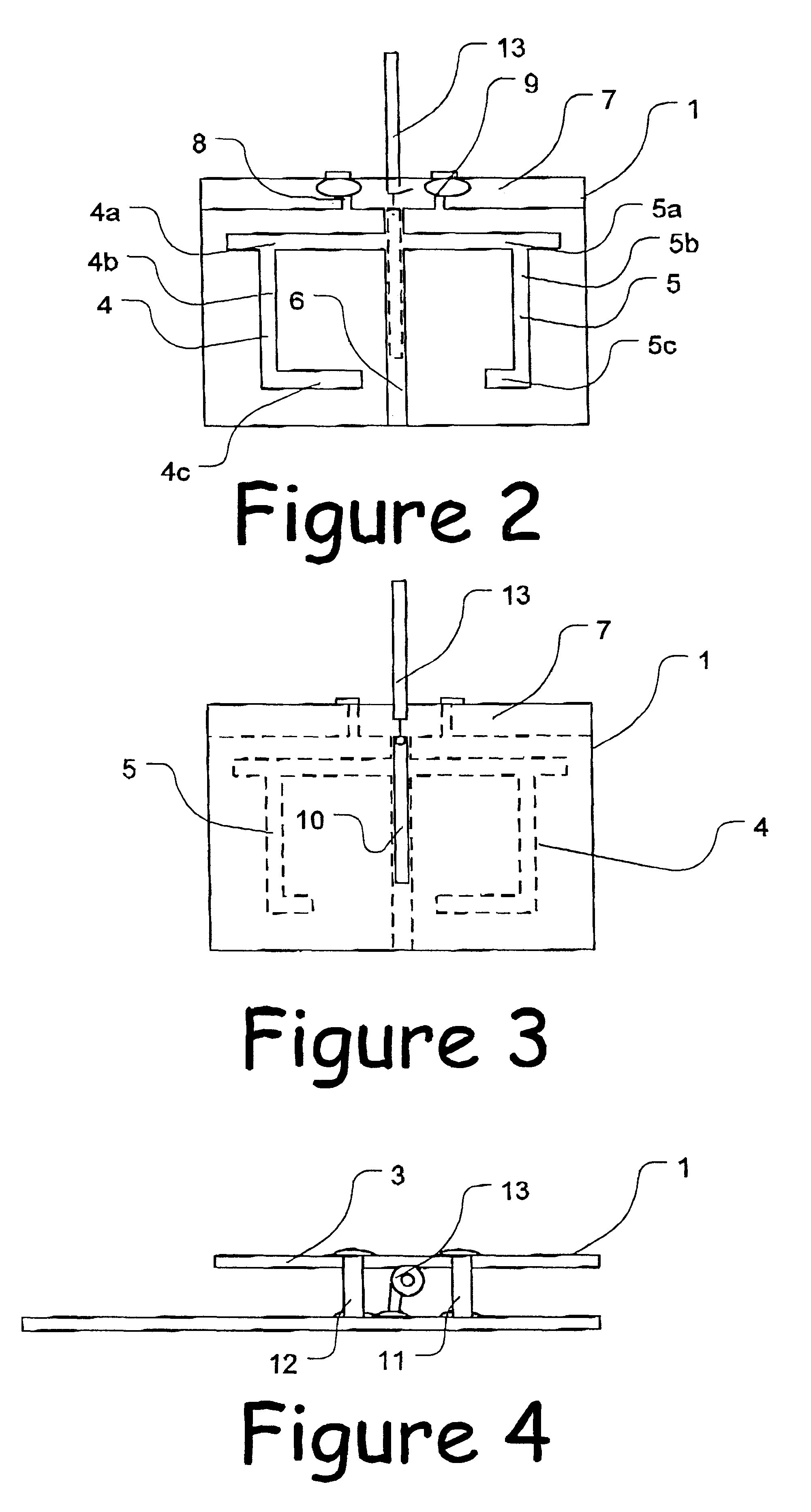
Referring to FIG. 1, an antenna 1 according to the present invention is mounted to the main printed circuit board (PCB) 2 of a radio communication device. The antenna 1 lies parallel to and is spaced perpendicularly from a major face of the main printed circuit board 2.

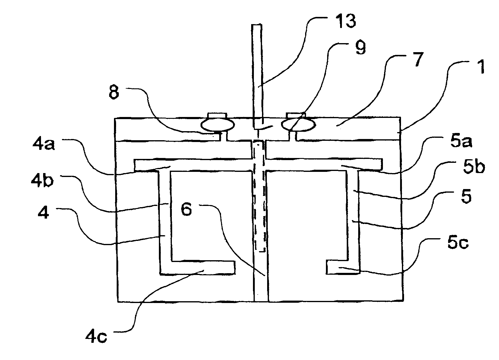
Referring to FIGS. 2 and 3, the antenna 1 comprises a substrate 3. First and second angular, substantially C-shaped, slots 4, 5 are on one side of the substrate 3. The slots 4, 5 extend in opposite directions from a central strip 6, extending across the printed circuit board 3. Both the central strip and the slots 4, 5 comprise regions from which copper of a conductive layer on the substrate 3 has been removed. The copper conductor has also been removed from a margin 7 of the printed circuit board 3 which runs perpendicular to the central strip 6, except for two branches 8, 9 reaching to the edge ...


PUM


Abstract

An antenna has at least one slotted planar element. The slot in the planar element is open at one end and configured such that the planar element has a quarter wave resonance mode at a first frequency and there is a second resonant frequency at which the element has a 3 / 4 wave resonance mode and / or the element's slot has a quarter wave resonance mode. The second frequency is not substantially three time the first frequency. Multiple slotted elements may be employed to achieve increased bandwidth.

Description

FIELD OF THE INVENTIONThe present invention relates to a multiband antenna.BACKGROUND TO THE INVENTIONIn recent years there has been a move towards harmonizing mobile phone systems throughout the world. For Instance, many countries have GSM900 systems enabling users from one country to use their mobile phones in another country. However, this harmonization has not yet been completed. For instance, spectrum availability has lead to the introduction of DCS1800 which is similar to GSM900 but operates in a band In the region of 1800 MHz rather than 900 MHz as in the case of GSM. Additionally, national spectrum management authorities do not necessarily decide to allocate the same bands to the public land mobile network service. For instance, in the United States of America a DCS1SOO-like system (DCS1900) is implemented in a band in the region of 1900 MHz. Further Incompatibilities arise during transitional periods when a new system is being introduced and an old one phased out.SUMMARY OF...

Claims


Application Information

Patent Timeline
Patent Type & Authority Patents(United States)
IPC IPC(8): H01Q13/10H01Q1/24H01Q5/00H01Q5/371
CPCH01Q1/243H01Q5/371H01Q13/106
Inventor WANG, HANYANGZHANG, SU QUING
Owner NOKIA CORP
Learn More