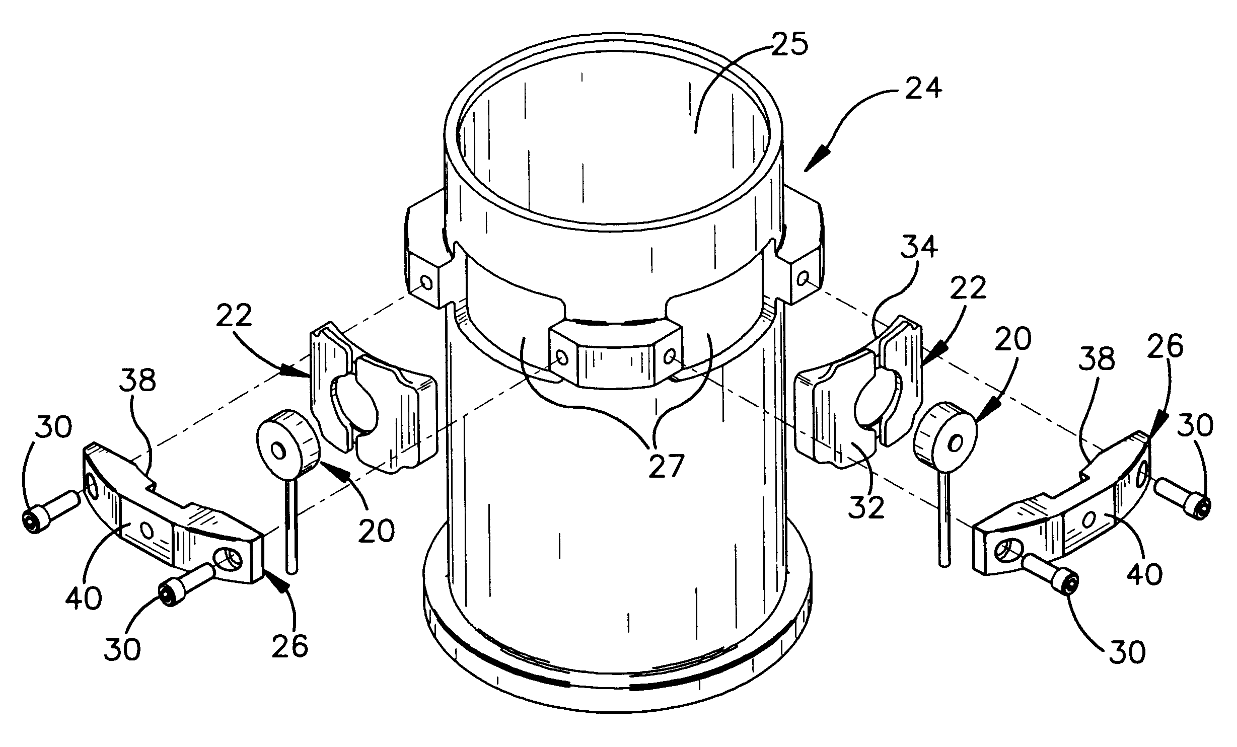
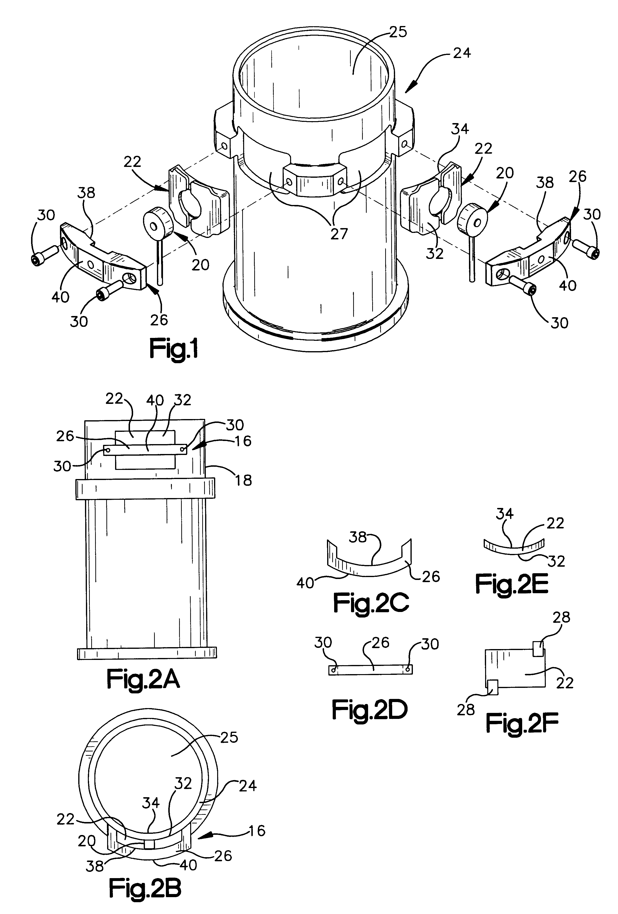
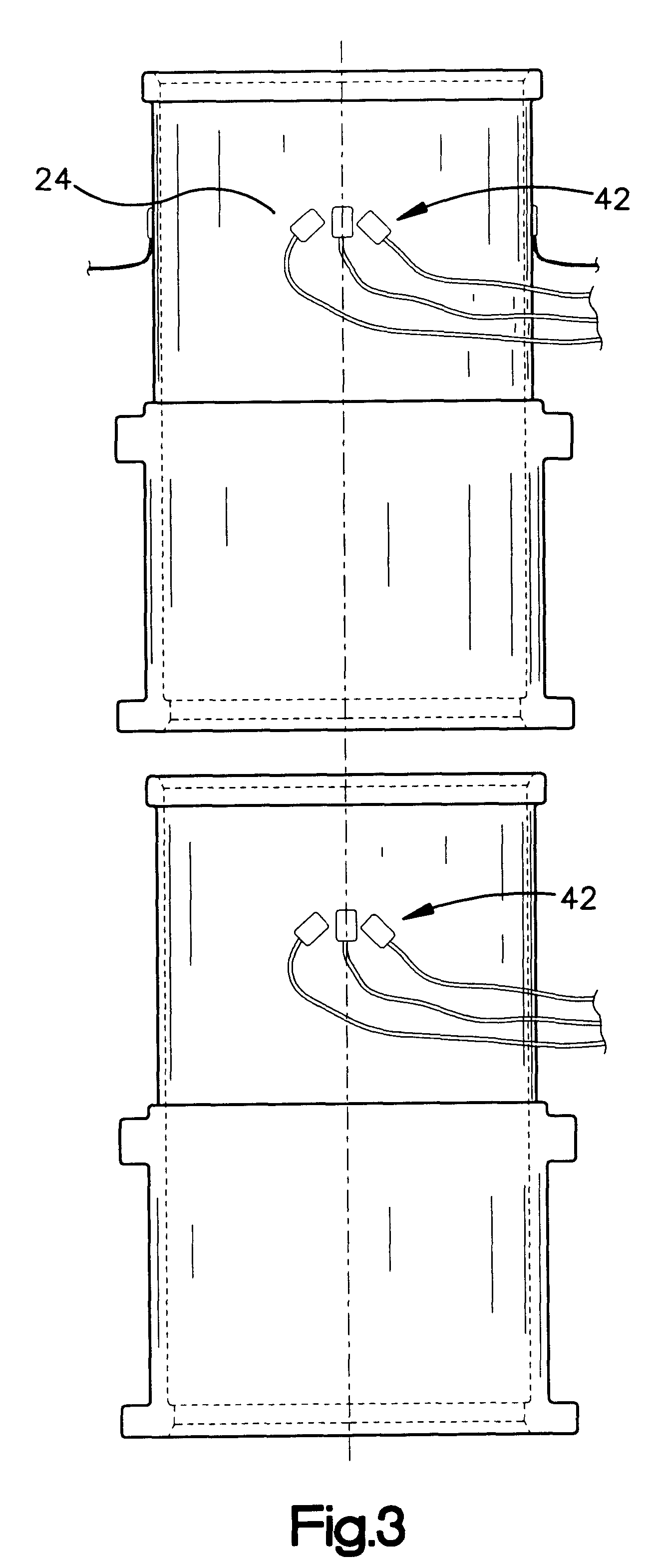
Instrumented mold for use in material testing equipment for measurement of material properties

a technology of material properties and instruments, which is applied in the direction of instruments, measurement devices, scientific instruments, etc., can solve the problems of not being able to predict the rutting potential of asphalt mixes in a way, unable to account for lateral forces, and difficult to detect or measure the forces exerted by materials in multiple dimensions or directions

Inactive Publication Date: 2003-09-23
PINE INSTR +1
View PDF9 Cites 28 Cited by
  • Summary
  • Abstract
  • Description
  • Claims
  • Application Information

AI Technical Summary

Benefits of technology

It is therefore an object of the present invention to provide a tool that can be used to: determine rutting potential of mixes; to determine tenderness potential of mixes; to determine ideal design air voids for different mixes; to compare different asphalt binders; to compare different aggregates; to compare different gradations; and to control quality of mixes during production and laydown.

Problems solved by technology

One inherent limitation of such testing is that by confining a material specimen within a rigid structure such as a mold, it is difficult to detect or measure forces exerted by the material in multiple dimensions or directions.
This type of measurement does not account for the lateral forces acting against the cavity walls.
Because the walls of the mold are rigid, such testing methods do not account for reaction of the material laterally against the mold walls, or in directions other than along the axis of compression.
However, no theory or equipment has so far been completely successful in predicting rutting potential of asphalt mixes in a way which matches the performance of in-place mixes.

Method used


Image

  • Instrumented mold for use in material testing equipment for measurement of material properties
  • Instrumented mold for use in material testing equipment for measurement of material properties
  • Instrumented mold for use in material testing equipment for measurement of material properties

Examples


Embodiment Construction

A simple way of measuring the shear strength in a composite material is through the measurement of lateral pressure that is generated due to a vertical pressure. For example, a solid block of steel, loaded below its crushing strength, would develop almost negligible lateral pressure under a vertical stress, whereas in a mass of water, with no shear strength, the lateral pressure that is developed due to a vertical pressure is equal to the vertical pressure. The example of these two extreme cases illustrate that for a material which lies, in material properties, somewhere between a solid block of steel and mass of water, the higher the lateral pressure due to a vertical pressure, the lower the shear strength of the material.

In soil mechanics, it is well known that a soil with rounded aggregates would result in a low angle of internal friction (.phi.), and hence a low shear strength. From the concepts of lateral pressure developed in soil (as applied to retaining walls, for example), ...


PUM

PropertyMeasurementUnit
sizeaaaaaaaaaa
sizeaaaaaaaaaa
reactive forcesaaaaaaaaaa

Abstract

A system and method for measuring forces and behavior of a material when subjected to an applied force in a contained vessel or mold in directions not aligned with the applied force. Materials which flow, including mixed materials with an aggregate and a mastic, can be tested within a material vessel or mold by applying a force to the material within the mold and, in addition to measuring resistance of the material to the applied force, resulting forces applied by the material to the mold walls, for example laterally relative to the applied force, are measured and are indicative of flow characteristics and load bearing performance, and shear strength of the material. In a specific testing device, a material testing mold for use with material testing equipment which applies forces to material within the mold, has a mold cavity formed by walls. At least one portion of the wall is configured to deflect or deform in response to material pressure created by a force applied to the material. Deflection or deformation of the mold wall is measured to provide an indication of force transfer load bearing properties and behavior of the material in the mold, which is indicative of real world performance.

Description

The present invention pertains generally to materials testing and, more particularly, to machinery and methods for applying forces to materials and measuring material responses to applied forces.Materials testing frequently involves subjecting a material specimen, held in a container or mold, to a variety of forces and analyzing the material response to such forces. In certain types of materials testing equipment, material is held in a rigid cavity or vessel and subjected to substantial force. One inherent limitation of such testing is that by confining a material specimen within a rigid structure such as a mold, it is difficult to detect or measure forces exerted by the material in multiple dimensions or directions. The mold allows measurement of a material response in only a single dimension, which yields data on only certain properties of the material. Measurement of material response in multiple dimensions can yield valuable information on material properties, and in some cases ...

Claims


Application Information

Patent Timeline
Patent Type & Authority Patents(United States)
IPC IPC(8): G01N3/08G01N3/02G01N3/00
CPCG01N3/08G01N2203/0094G01N2203/0256G01N2203/0284
Inventor MALLICK, RAJIB B.TETO, MATTHEW R.
Owner PINE INSTR
Why Eureka
Try Eureka