
Minimally Invasive Systems and Methods for In Vivo Testing of Materials

a technology of in vivo testing and minimal invasive systems, applied in chemical methods analysis, biomass after-treatment, instruments, etc., can solve problems such as disruption of study, difficulty in retaining material, and trauma to the animal

Inactive Publication Date: 2011-03-03
TARIS BIOMEDICAL
View PDF6 Cites 23 Cited by
  • Summary
  • Abstract
  • Description
  • Claims
  • Application Information

AI Technical Summary

Benefits of technology

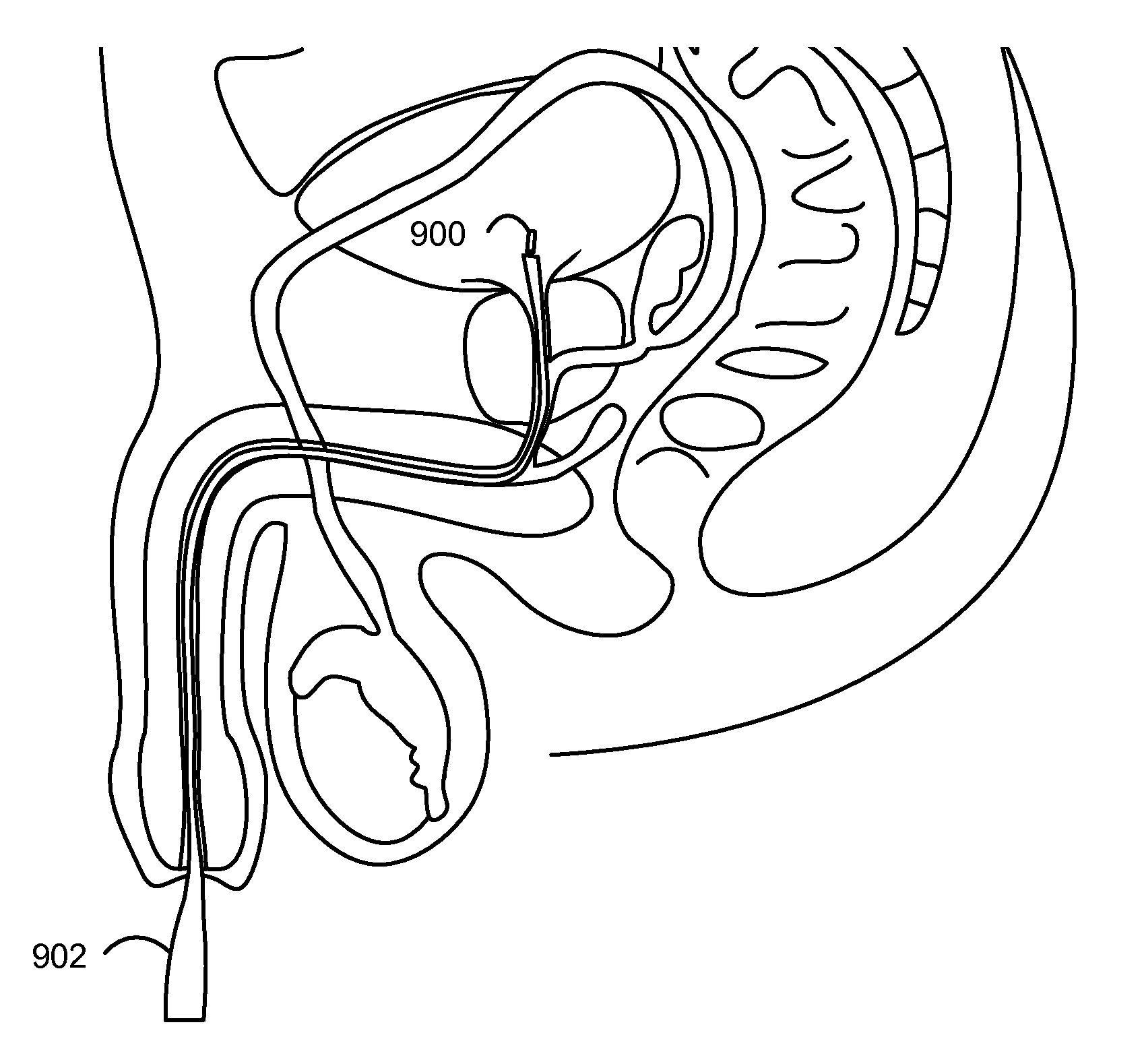
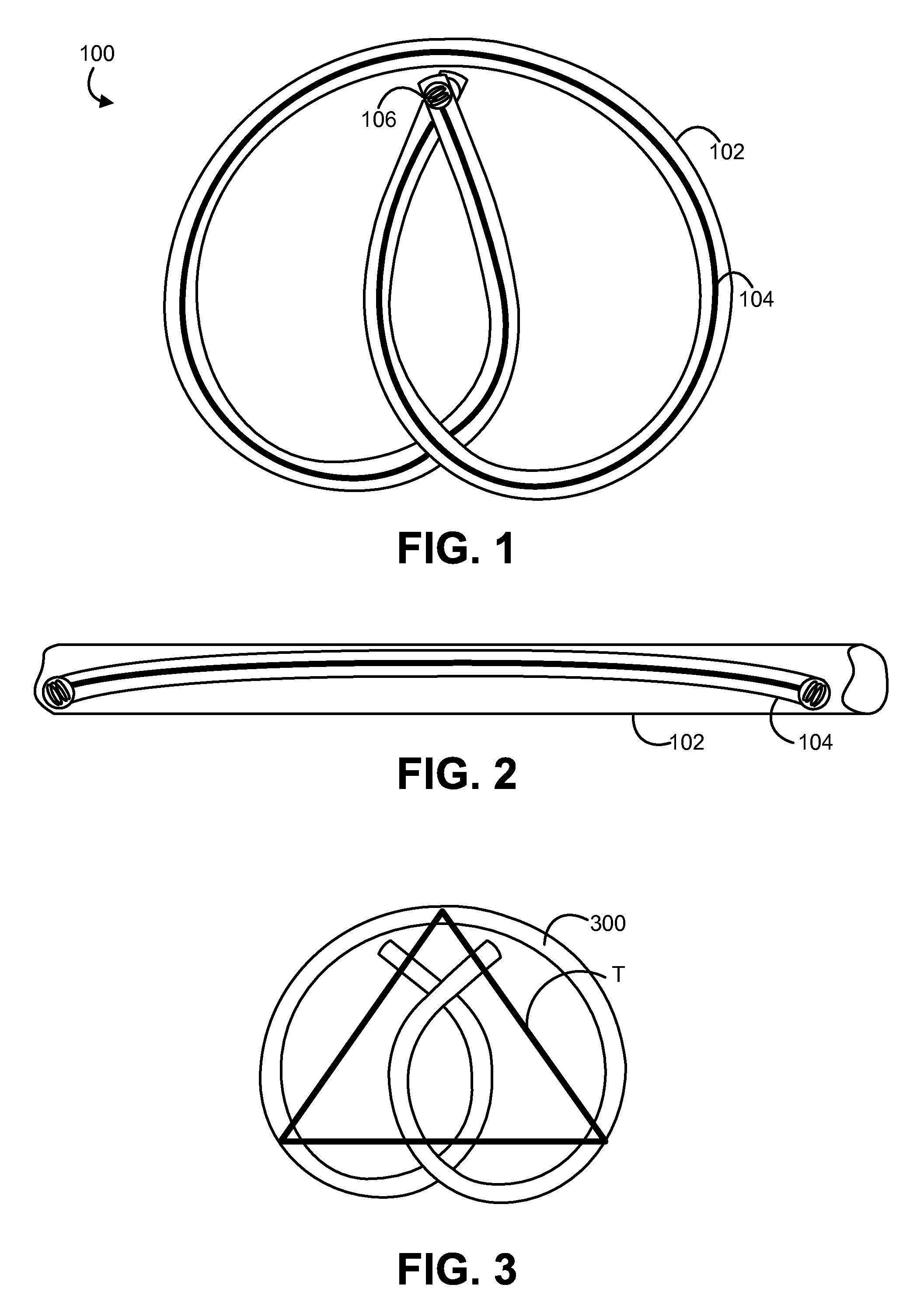
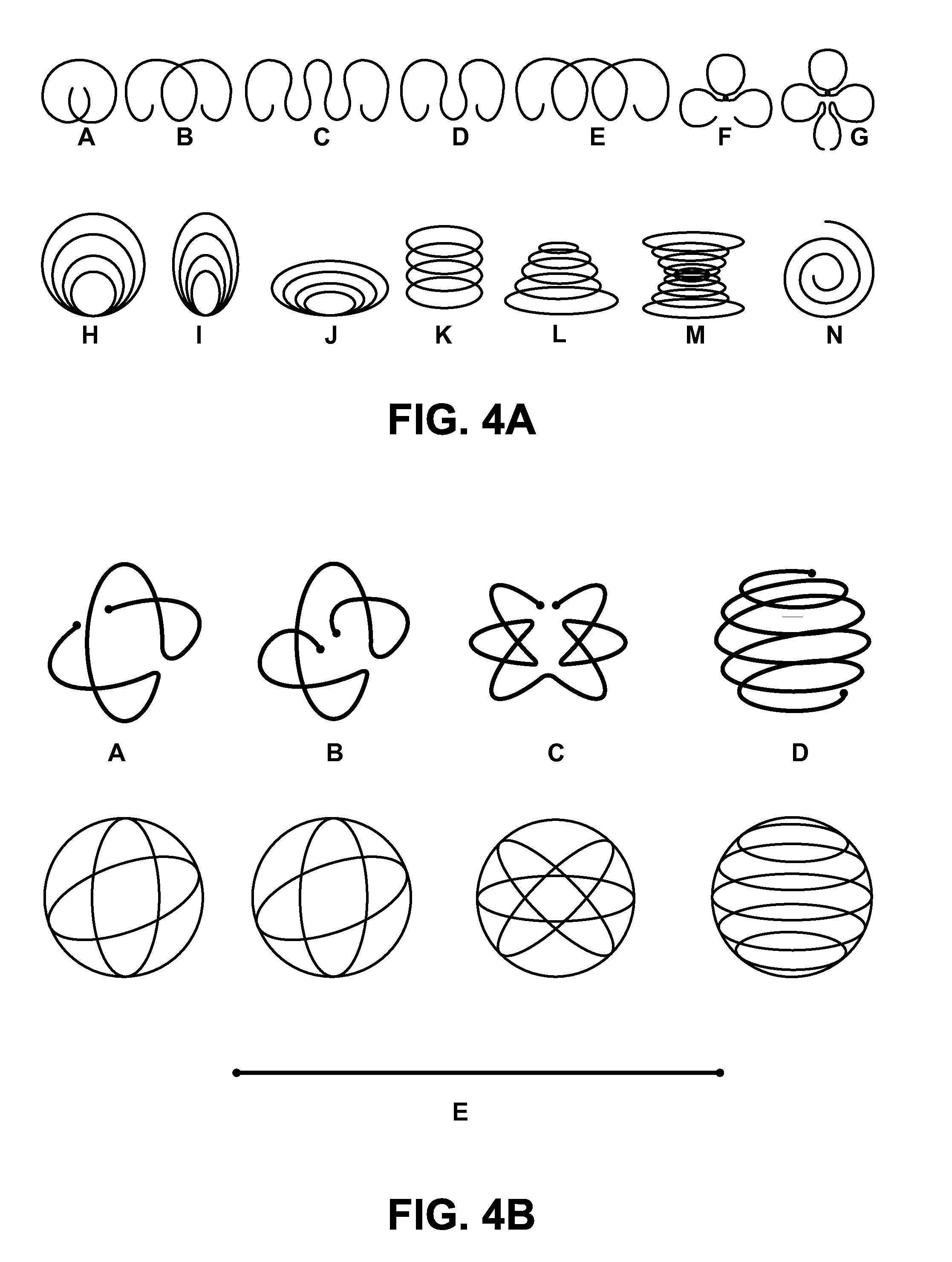
The patent describes a method and device for testing materials in animals. The testing device is made up of a retention frame and a material portion. The retention frame can be moved between two shapes: a first shape for insertion through a deployment instrument and a second shape for retention in the animal. The testing device is inserted into the animal through the deployment instrument and allowed to assume the second shape for a testing period. The testing device can be removed from the animal after the testing period is complete, and the material can be analyzed. The testing period can be between 1 day and 90 days. The material testing device can be used to test materials in the bladder or body cavity of an animal. The retention frame can be made of elastic wire or a shape memory material, such as nitinol wire. The technical effects of this patent include providing a minimally invasive method for testing materials in animals, allowing for longer testing periods, and the ability to test materials in different body cavities.

Problems solved by technology

However, surgically implanting the materials is cumbersome and causes trauma to the animal.
The animal also may have difficulty retaining the material in the bladder without accidental voiding, which disrupts the study.

Method used


Image

  • Minimally Invasive Systems and Methods for In Vivo Testing of Materials
  • Minimally Invasive Systems and Methods for In Vivo Testing of Materials
  • Minimally Invasive Systems and Methods for In Vivo Testing of Materials

Examples


example 1

Sample Spring Constants for Certain Low Modulus Wires

[0078]A nitinol wire having a Young's modulus of about 30 GPa, a diameter of about 0.2286 mm, an arc radius of about 1.5 cm, and one coil may have a spring constant of about 3.7 N / m. A polyurethane wire having a Young's modulus of about 25 MPa, a diameter of about 1 mm, an arc radius of about 1 cm, and one coil may have a spring constant of about 3.8 N / m. A silicone wire having a Young's modulus of about 2.41 MPa, a diameter of about 1.2 mm, an arc radius of about 0.75 cm, and two coils may have a spring constant of about 3.6 N / m. A poly(glycerol-sebacate) (PGS) wire having a Young's modulus of about 1.7 MPa, a diameter of about 1.2 mm, an arc radius of about 0.76 cm, and three coils may have a spring constant of about 3.7 N / m.


PUM

PropertyMeasurementUnit
diameteraaaaaaaaaa
diameteraaaaaaaaaa
sizeaaaaaaaaaa

Abstract

Implantable material testing devices and method of testing materials in an animals are provided. In one embodiment, a method of testing a material in an animal includes associating the material with a retention frame to form a testing device. The retention frame movable between a first shape suited for insertion through a deployment instrument and a second shape suited for retention in the animal. The testing device is inserted in the first shape into the deployment instrument and is driven through the deployment instrument into the animal. Once in the animal, the testing device is permitted to assume the second shape so that the testing device is retained in the animal for a testing period. The testing device is removed from the animal after the testing period is complete, and the material is analyzed. The material may be analyzed for biofilm formation, encrustation, or degradation. The animal also may be analyzed for infection or other reactions to the material. Tissue may be collected from the animal, and the tissue may be analyzed. The testing period may be between about 1 day and about 90 days.

Description

CROSS-REFERENCE TO RELATED APPLICATIONS[0001]This application claims the benefit of U.S. Provisional Application No. 61 / 237,517, filed Aug. 27, 2009, which is incorporated herein by reference in its entirety.BACKGROUND OF THE INVENTION[0002]Genitourinary devices and equipment are typically formed from materials that are suited for use in the genitourinary system. For example, urological devices and equipment such as ureteral stents, urethral stents, and urethral catheters often include materials such as natural or synthetic polymeric compounds, coatings, and surface treatments. To investigate the suitability of these materials for use in humans, these materials are often tested before human use to ensure biocompatibility and to identify the risk of undesirable effects such as biofilm formation, infection, and encrustation. Typically, both in vitro analysis and in vivo animal testing are performed. In vivo animal testing usually involves implanting the materials in animal models, suc...

Claims


Application Information

Patent Timeline
Patent Type & Authority Applications(United States)
IPC IPC(8): A61K49/00C12Q1/02C12M1/34G01N31/00
CPCA61M2210/1085A61M31/002
Inventor LEE, HEEJIN
Owner TARIS BIOMEDICAL
Learn More