Testing device for current auxiliary type micro-stretching mechanical property of metal thin plate

A metal sheet and testing device technology, which is used in measuring devices, using stable tension/pressure to test the strength of materials, scientific instruments, etc., to achieve the effects of remarkable cooling effect, accurate measurement results, and simple fixture structure

Active Publication Date: 2015-04-08
HARBIN INST OF TECH
View PDF5 Cites 24 Cited by
  • Summary
  • Abstract
  • Description
  • Claims
  • Application Information

AI Technical Summary

Problems solved by technology

[0003] The purpose of the present invention is to solve the problems that there is no relevant information at home and abroad for reference, and it is necessary to solve the problems of energization and insulation of the micro-tensioning fixtur

Method used


Image

  • Testing device for current auxiliary type micro-stretching mechanical property of metal thin plate
  • Testing device for current auxiliary type micro-stretching mechanical property of metal thin plate
  • Testing device for current auxiliary type micro-stretching mechanical property of metal thin plate

Examples


specific Embodiment approach 1

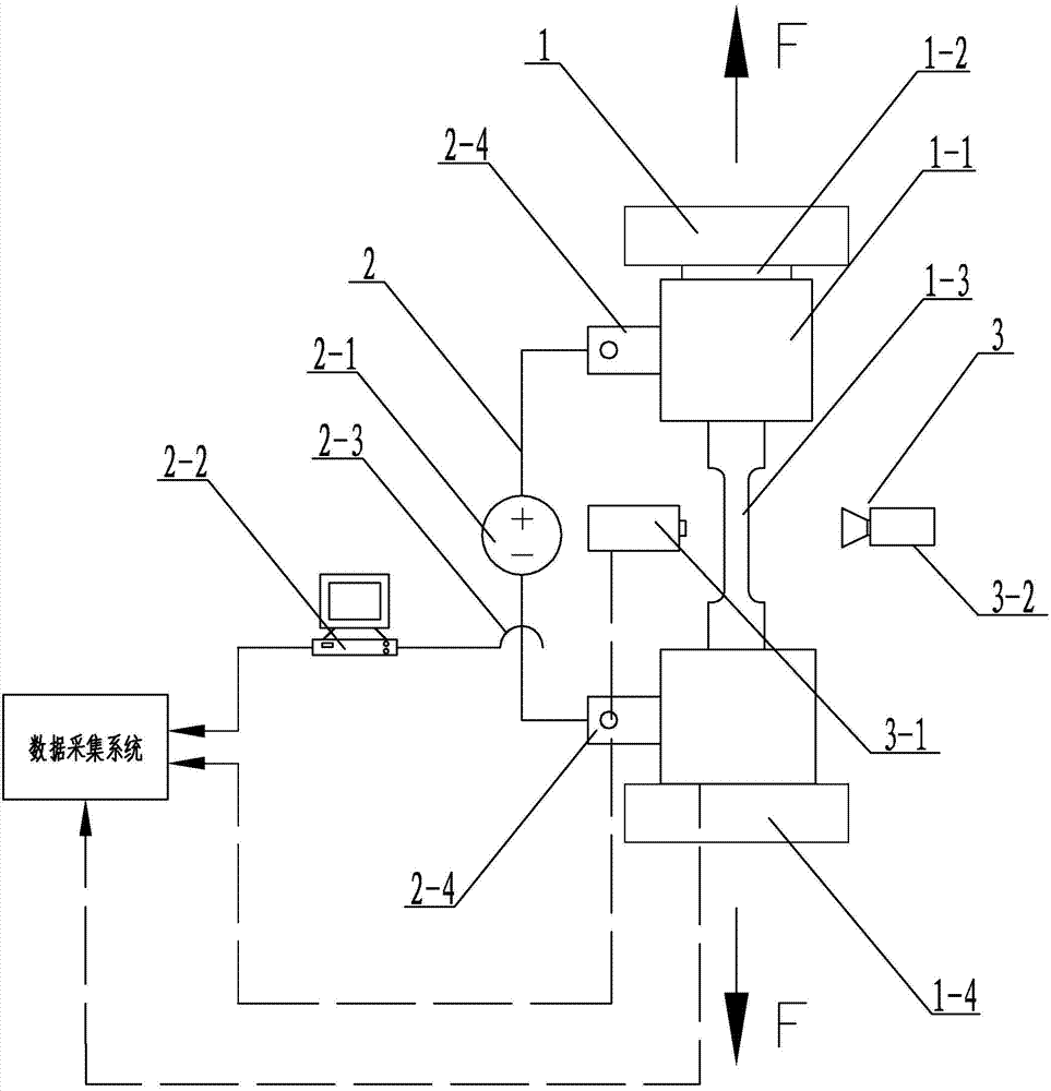
[0015] Specific implementation mode one: combine figure 1 , figure 2 and image 3 Describe this embodiment mode, a kind of metal thin plate electric current assisted micro-tensile mechanical performance testing device of this embodiment mode comprises uniaxial tensile test device 1, electric current generation and electrical parameter acquisition device 2 and temperature control and temperature acquisition device 3, described The unidirectional tensile test device 1 includes two sets of clip bodies 1-1, force sensors 1-2 and universal material testing machine 1-4, the force sensor 1-2 is installed on the lower part of the universal material testing machine 1-4 moving beam, two groups The clamp body 1-1 is symmetrically installed on the universal material testing machine 1-4 through a pin connection, the micro-tensile sample 1-3 is installed between two sets of clamp bodies 1-1, and the current generation and electrical parameter acquisition device 2 includes a pulse Power s...

specific Embodiment approach 2

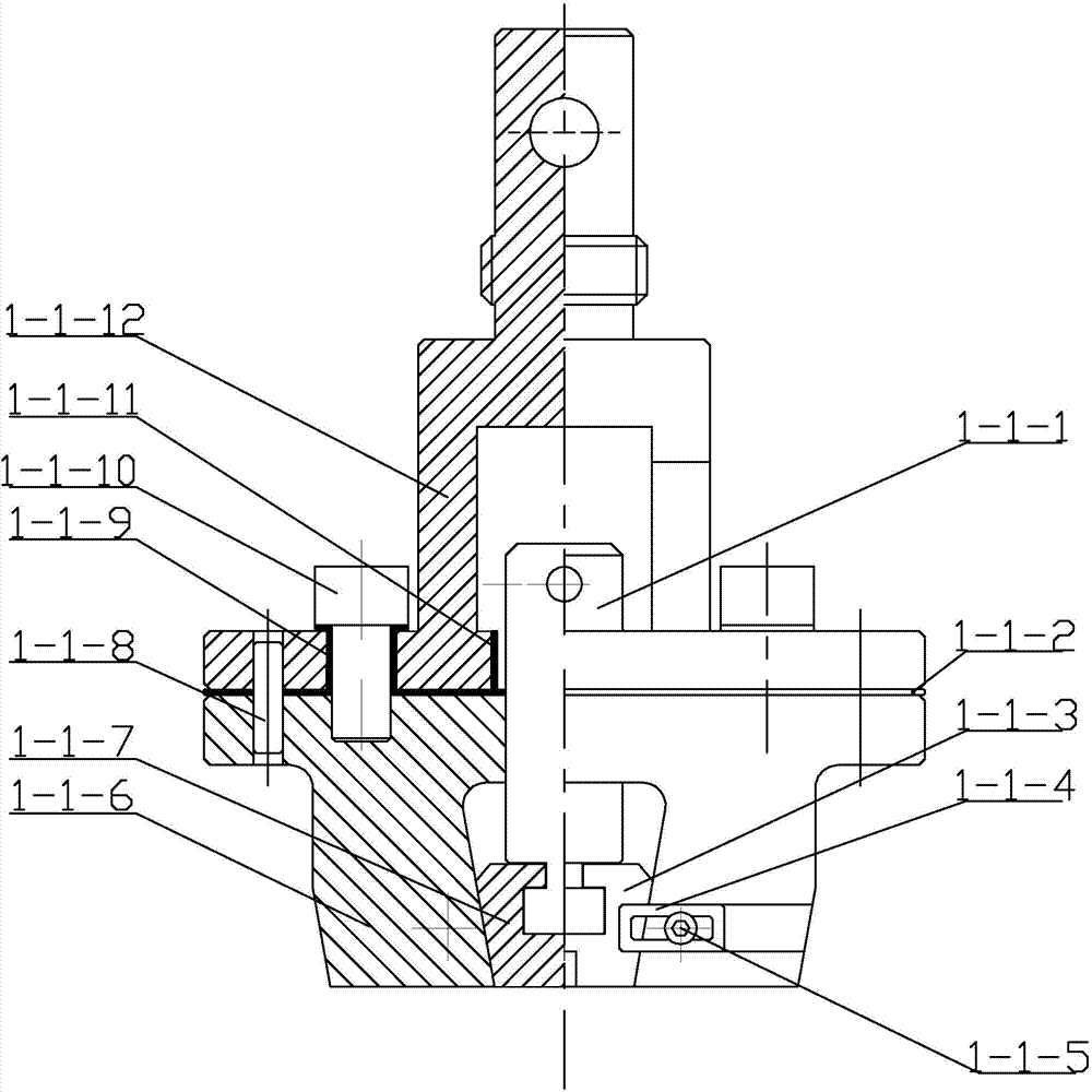
[0017] Specific implementation mode two: combination figure 2 To illustrate this embodiment, each group of clamp bodies 1-1 in the two sets of clamp bodies 1-1 of this embodiment includes a pressure plate 1-1-1, a mica insulating plate 1-1-2, and a right wedge-shaped clamp block 1-1 -3. Baffle plate 1-1-4, lower clamp body 1-1-6, left wedge clamp block 1-1-7, upper clamp body 1-1-12, two first insulating sleeves 1-1- 9. The second insulating sleeve 1-1-11 and two alumina ceramic insulating tapered pins 1-1-8.

[0018] The pressure plate 1-1-1 is screwed on the threaded hole of the lower clamp body 1-1-6, and the upper clamp body 1-1-12 is tightened with the lower clamp body 1-1-6 through two hexagon socket bolts 1-1-10. The mica insulation board 1-1-2 is arranged between the upper clamp body 1-1-12 and the lower clamp body 1-1-6, and the upper clamp body 1-1-12 and the lower clamp body 1-1- 6 Positioning by two alumina ceramic insulating tapered pins 1-1-8, each first insul...

specific Embodiment approach 3

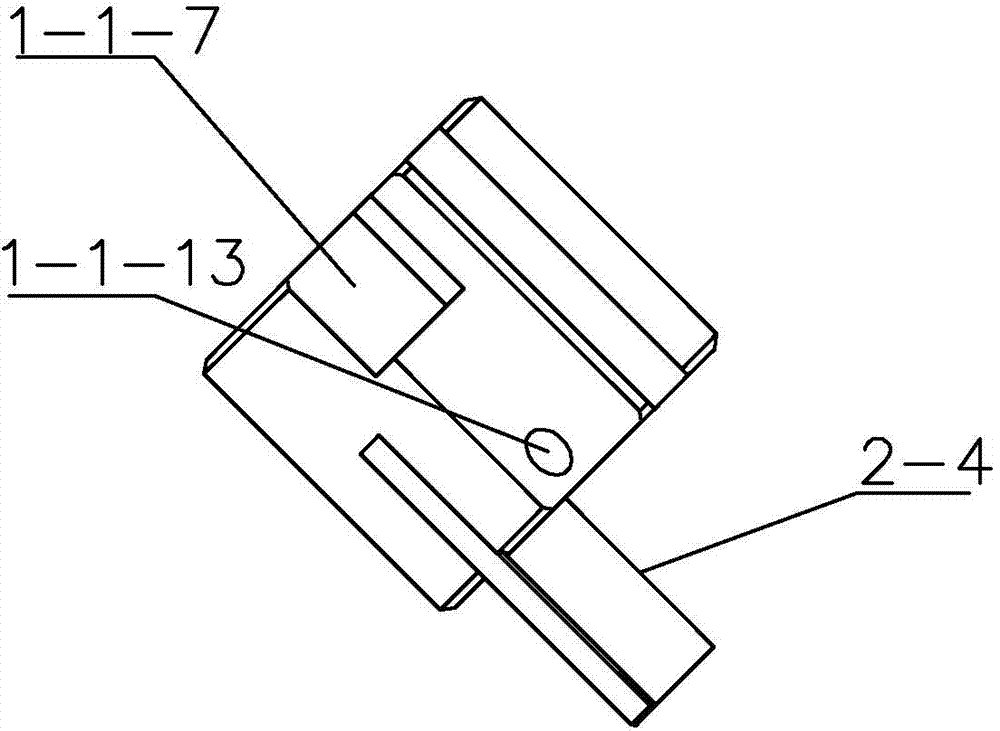
[0021] Specific implementation mode three: combination figure 2 To illustrate this embodiment, the clamping planes of the left wedge-shaped clamping block 1-1-7 and the right wedge-shaped clamping block 1-1-3 of this embodiment are provided with serrations. Such setting increases the coefficient of static friction between the micro-tensile sample and the wedge clamp. Other compositions and connections are the same as those in Embodiment 1 or Embodiment 2.


PUM


Abstract

The invention provides a testing device for a current auxiliary type micro-stretching mechanical property of a metal thin plate and relates to a mechanical property testing device. As no relative information can be referred at home and abroad at present, the problems of electrification and insulation of a micro-stretching clamp, a clamping form of a micro-test sample, control and acquisition of the temperature of the test sample, and current parameter acquisition are required to be solved. A force sensor is mounted at the lower part of a movable transverse beam of an all-purpose material testing machine; two sets of clamp bodies are symmetrically mounted on the all-purpose material testing machine; a micro-stretching test sample is mounted between the two sets of clamp bodies; the two ends of a pulse power supply are connected with the two sets of clamp bodies by purple copper electrodes; a digital storage type oscilloscope is connected with the pulse power supply through a Hall current probe; a loop is formed by the pulse power supply, the two purple copper electrodes, the two sets of clamp bodies and the micro-stretching test sample; and a thermal infrared imager and an industrial air blower are mounted on the two sides of the all-purpose material testing machine by brackets. The testing device is used for current auxiliary type micro-stretching mechanical property testing.

Description

technical field [0001] The invention relates to a micro-tensile mechanical property testing device, in particular to a metal sheet current-assisted micro-tensile mechanical property test device, which belongs to the field of micro-tensile mechanical property testing. Background technique [0002] Under the action of electricity, the deformation resistance of the material decreases and the plasticity increases, which is called the electroplastic effect. Since the discovery of the electroplastic effect in the 1960s, scholars at home and abroad have carried out a lot of research on the mechanism of electroplasticity and its forming process. Compared with the traditional warm forming process, the current-assisted plastic forming process has the advantages of short forming cycle, energy saving, and environmental protection. At present, domestic Tsinghua University and Yanshan have developed electroplastic drawing devices, and Shanghai Jiaotong University has also developed elect...

Claims


Application Information

Patent Timeline
IPC IPC(8): G01N3/18G01N3/02G01N3/04
Inventor 徐杰郭斌单德彬刘勇达王春举
Owner HARBIN INST OF TECH
Why Eureka
Try Eureka