Needle free access valve

Inactive Publication Date: 2003-09-30
OCCUPATIONAL & MEDICAL INNOVATIONS
View PDF13 Cites 56 Cited by
  • Summary
  • Abstract
  • Description
  • Claims
  • Application Information

AI Technical Summary

Benefits of technology

The present invention is directed to a needle-free access valve which can be swabbed and sterilised between use, and which may at least partially overcome some of the abovementioned disadvantages or provide the consumer with useful or commercial choice.
In a third embodiment, the valve assembly comprises a single valve member which may comprise a head part and a stem part and the biasing means may comprise a helical spring about the stem part. In this embodiment, the head part may slide along the tubular passageway between a closed position where the head part is substantially at the inlet, and an open position where the head part is pushed downwardly along the tubular passageway. The tubular passageway may be provided with at least one recess spaced away from the inlet to facilitate fluid flow past the head part.

Problems solved by technology

With conventional valves, the tubular passageway remains completely open as the valve is usually at the bottom of the tubular passageway, and such an open passageway is a source of contamination which is difficult if not impossible to properly sterilise.

Method used


Image

  • Needle free access valve
  • Needle free access valve
  • Needle free access valve

Examples


first embodiment

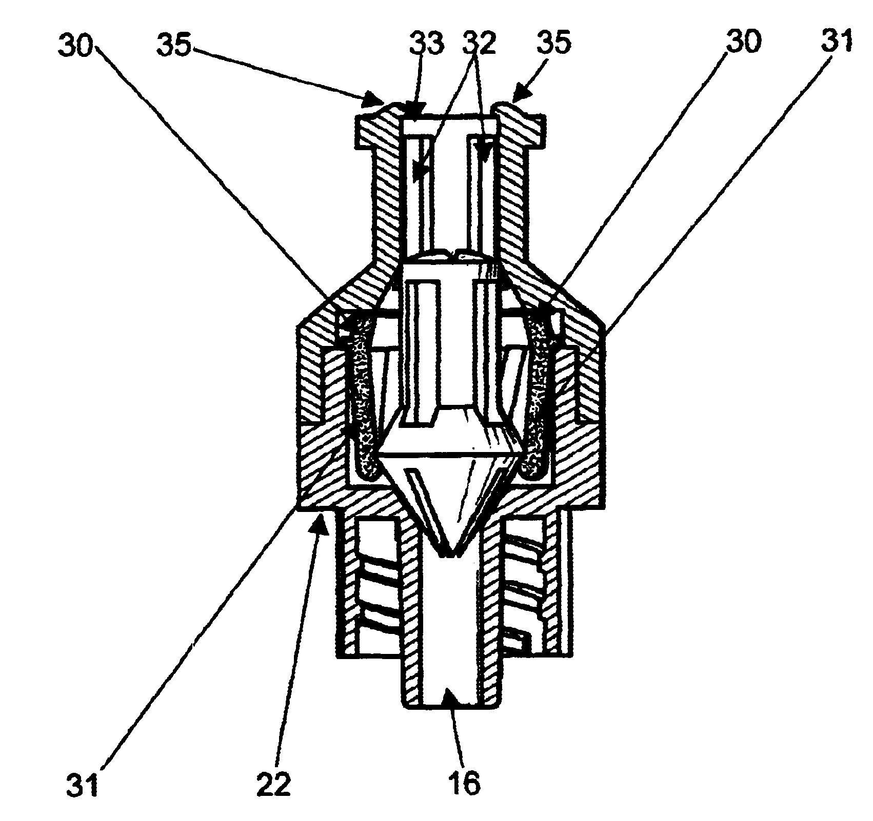
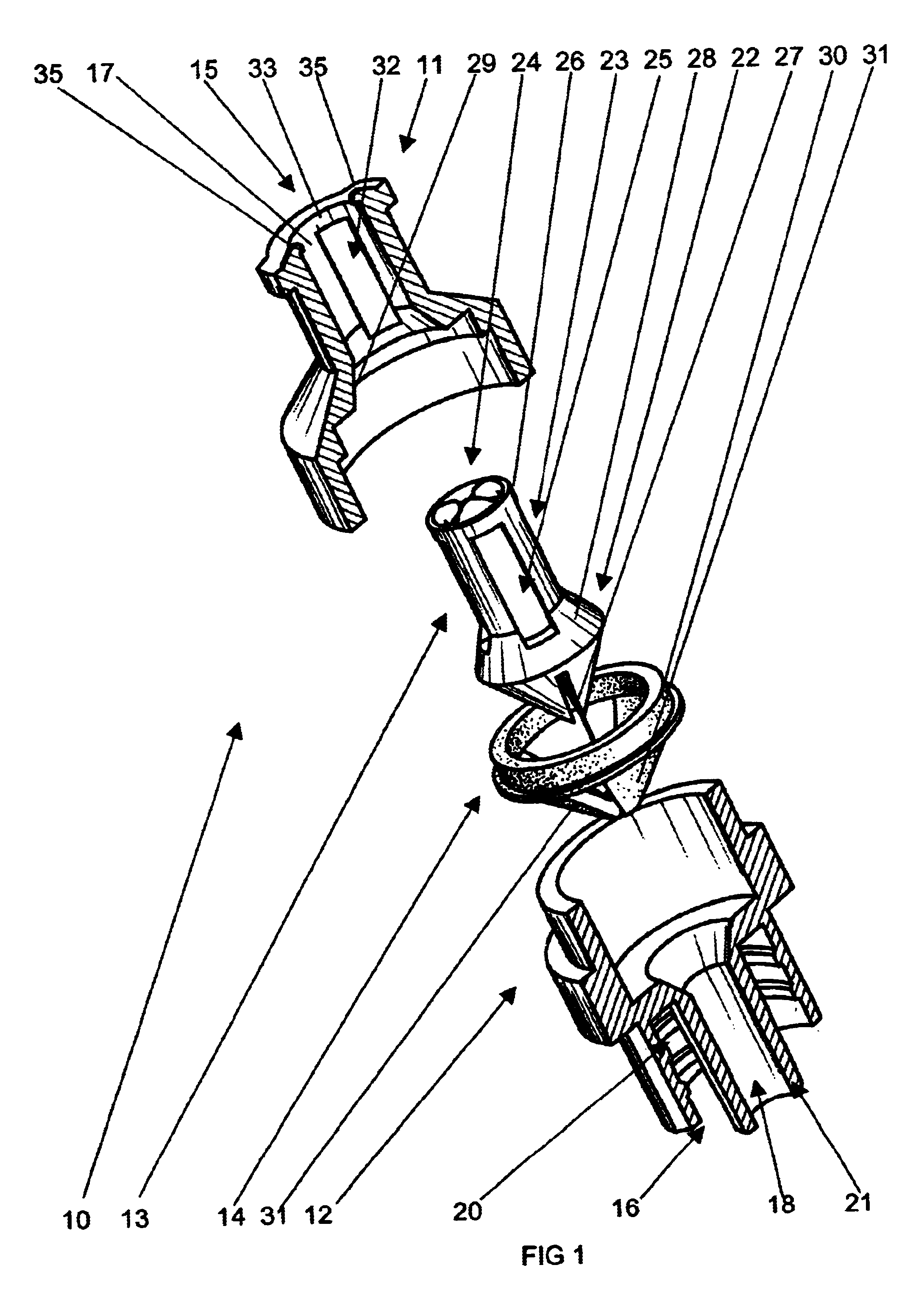
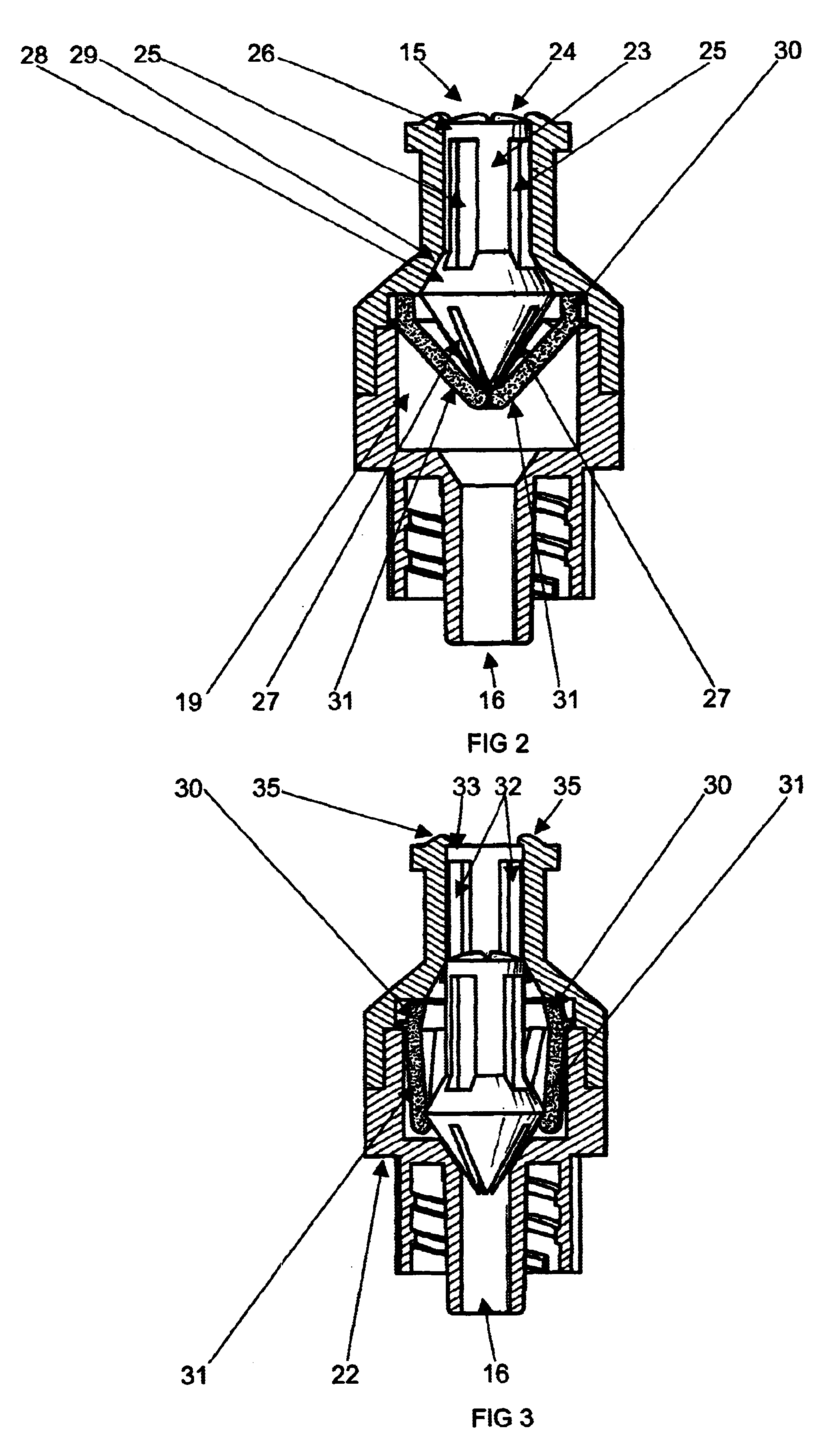
Referring initially to the invention illustrated in FIGS. 1-4, there is disclosed a valve assembly 10. The valve assembly is made from four separate components which comprise an external housing which consists of a top casing 11 and a bottom casing 12, an internal valve member 13 and an internal biasing means 14. The housing can be made from polycarbonates or similar material. The top casing and the bottom casing are bonded together in a permanent seal. Each casing is substantially hollow to define an internal substantially circular passageway. Each casing has a stepped internal passageway. Top casing 11 has an inlet 15 while bottom casing 12 has an outlet 16. In top casing 11, inlet 15 communicates or forms part of a first tubular passageway 17 of smaller diameter, which opens up into a second tubular passageway of larger diameter. Similarly, bottom casing 12 has an outlet 16 which communicates or forms part of a first tubular passageway 18 of smaller diameter which opens up into a...

second embodiment

the invention is illustrated in FIGS. 5-8. In this embodiment, the valve assembly comprises a one-piece moulded housing 40 which has a standard luer lock 41 which forms part of the outlet. Housing 40 has a top inlet 42 which is provided with a pair of small barbed projections 35 similar to that described above. Inlet 42 forms part of an internal longitudinal passageway 43 which is best illustrated in FIGS. 5-6. Passageway 43 is circular and has an internal ring shaped stepped portion 44 the reason for which will be described below. In the second embodiment, the valve member is formed from two parts being an inner stationary part or peg 45 (see FIG. 7), and an outer part or cap 46 (see FIG. 7). Cap 46 is biased by a steel helical spring 47 (see FIG. 7) into a naturally closed position where cap 46 is substantially flush with inlet 42, this being best illustrated in FIG. 6. Cap 46 has an internal circular longitudinal passageway 48. Peg 45 has an outer end 49 and an inner end 50. Oute...

third embodiment

the invention is described with reference to FIGS. 9-12. In this embodiment, the valve assembly has an outer housing which is similar to that described with respect to the second embodiment and which has an inlet 60 and an outlet 61 the outlet having the standard luer lock arrangement. An internal passageway 62 is provided which is best illustrated in FIGS. 9 and 10. The internal passageway has a restriction or step 63 which functions to hold the valve member as will be described in greater detail below. The valve member 64 has a head or cap 65 and an elongate rod or peg 66 which is attached to cap 65 in a fixed manner. That is, cap 65 does not slide along peg 66 in the manner described with reference to the second embodiment. Instead, depression of cap 65 by the syringe will cause cap 65 to be pushed into passageway 62 and attached peg 66 will be depressed into the outlet area 61. Cap 65 again has a peripheral lip 80 which can be deformed and which overlies the edge of inlet 60 whe...


PUM


Abstract

A one way valve assembly has an inlet and an outlet, the inlet forming one end of a tubular passageway, a valve member which is slideable along the tubular passageway between a closed position where fluid is unable to flow through the valve assembly, and an open position, the valve member having an outer end and an inner end, and biasing means to bias the valve member to the closed position, characterized in that when the valve member is in the closed position, the outer end is substantially at the inlet of the valve assembly to close of the tubular passageway and to allow the inlet area to be sterilized.

Description

This invention is directed to a needle free access valve for use in a needle free intravenous access system, and where the valve permits bi-directional flow when open. The valve finds particular use in the medical field.A needle free access valve is one where the valve can be opened using a needleless syringe. A needleless syringe is a syringe where the needle has been removed such that the front of the syringe has only the luer taper or luer lock. Such valves are known but suffer from a number of disadvantages. A typical known valve has a body composed of two cylindrical containers. One container has a tubular opening into which the luer taper can be pressed. The other container has a tubular opening filled with a luer lock which allows the valve to be attached to various medical devices. Fluid flows through the luer taper upon depression of the syringe plunger and flows through the valve. The valve has a circular valve disk which can be forced open by the pressure of the fluid. Wh...

Claims


Application Information

Patent Timeline
Patent Type & Authority Patents(United States)
IPC IPC(8): F16K15/14A61M39/22A61M39/26
CPCA61M39/26F16K15/147
Inventor KIEHNE, BRUCE LEIGH
Owner OCCUPATIONAL & MEDICAL INNOVATIONS
Why Eureka
Try Eureka