
Therapeutic light source and method

a light source and light source technology, applied in the field of therapeutic light sources, can solve the problems of low activation efficiency of most pdt drugs at these wavelengths, high penetration depth of light, and unsuitability for superficial conditions, and achieve the effect of narrow bandwidth light over a large area and greater intensity

Inactive Publication Date: 2003-09-30
THE LOTUS GLOBAL GRP INC DBA GLOBALMED TECH CO
View PDF27 Cites 53 Cited by
  • Summary
  • Abstract
  • Description
  • Claims
  • Application Information

AI Technical Summary

Benefits of technology

The solution provides higher intensity and more efficient absorption by the affected tissue, reducing treatment time and preventing underlying skin damage, while being cost-effective for treating large external surfaces.

Problems solved by technology

However, the coefficient of absorption of many PDT drugs for PDT, and of human tissue, is relatively low in these wavelengths, so that the light will have a high penetration depth and is unsuitable for treating superficial conditions.
Moreover, the activation efficiency of most PDT drugs is low at these wavelengths and the light intensity available from fluorescent tubes is also comparatively low, which will lead to long treatment times.
This light source would be expensive to manufacture as the U-shaped tubes would have to be manufactured specifically for this application.

Method used


Image

  • Therapeutic light source and method
  • Therapeutic light source and method
  • Therapeutic light source and method

Examples


Embodiment Construction

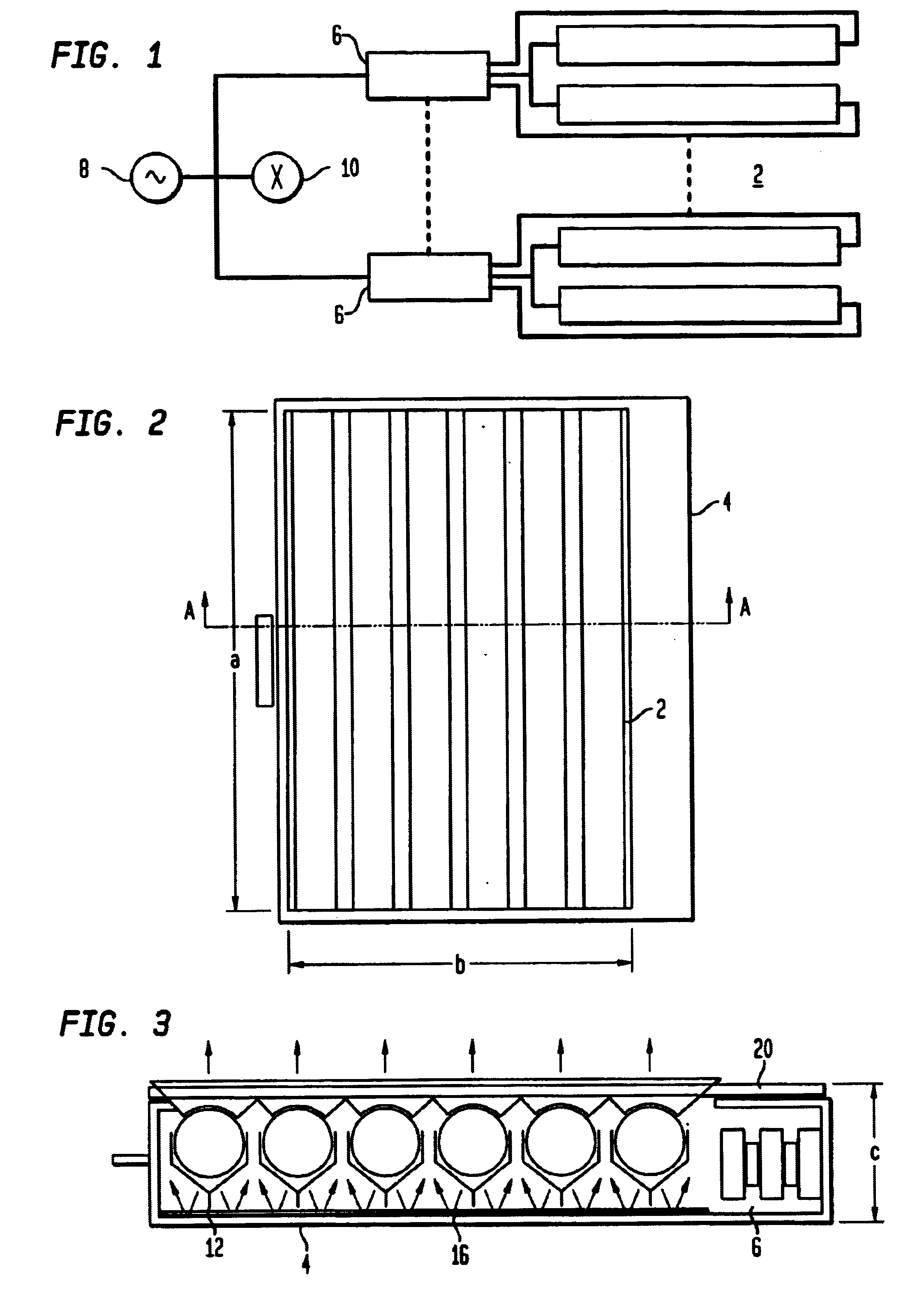
In an embodiment shown in FIGS. 1 to 3, six similar fluorescent tubes 2 are mounted parallel in an array in a generally cuboid hollow housing 4 made of polished stainless steel. The tubes 2 are electrically connected to electronic ballasts 6 for initiating and maintaining current flow through the tubes 2. The ballasts 6 are powered by an a.c. mains power supply 8. A fan 10, also driven by the mains power supply 8, is arranged to draw air through vents (not shown) in the housing 4 so as to cool the tubes 2.

Each of the tubes is securely engaged in a resilient mounting bracket 12 at each end attached to a back wall 14 of the housing 4. On the internal surface of the back wall 14 is a white diffuse reflector 16 arranged to reflect diffusely towards the front of the light emitted by the tubes 2. The diffuse reflector 16 may be made of a white self-adhesive plastic sheet (e.g. Fablon.TM.) or a removable sheet of paper or other material which can easily be replaced if it becomes dirty. Ins...


PUM

PropertyMeasurementUnit
wavelengthsaaaaaaaaaa
arc lengthaaaaaaaaaa

Abstract

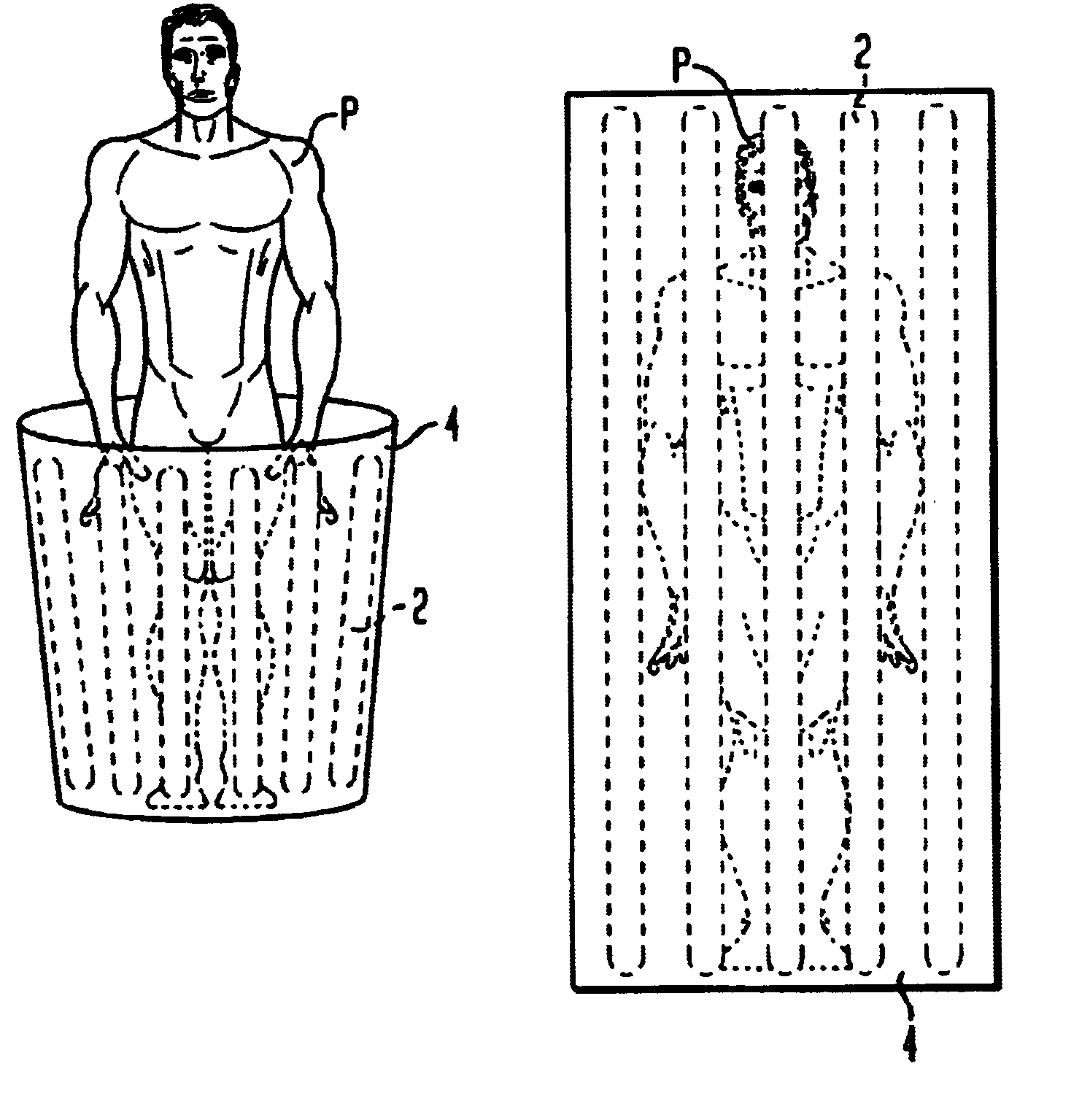
A light source for therapy, such as photodynamic therapy, comprises one or more low pressure or medium / high pressure discharge tubes. In one aspect, the light source comprises a non-planar array of substantially straight tubes. In another aspect, the light source comprises one or more such tubes mounted in a housing having an aperture allowing part of the patient to be located within the housing.

Description

The present invention relates to a non-coherent light source for use in therapy such as photodynamic therapy (PDT), particularly but not exclusively for treating large external surfaces of a patient, and / or a method of use thereof.Photodynamic therapy involves the administration of a photosensitising drug to an affected area, and its subsequent irradiation with light--see for example `The Physics of Photodynamic Therapy` by B C Wilson and M S Patterson, Physics in Medicine & Biology 31 (1986) April No. 4, London GB.The document WO 97 / 40888 proposes the use of one or more fluorescent tubes to emit yellow, orange and / or red wavelengths in a lamp for PDT. However, the coefficient of absorption of many PDT drugs for PDT, and of human tissue, is relatively low in these wavelengths, so that the light will have a high penetration depth and is unsuitable for treating superficial conditions. Moreover, the activation efficiency of most PDT drugs is low at these wavelengths and the light inten...

Claims


Application Information

Patent Timeline
Patent Type & Authority Patents(United States)
IPC IPC(8): A61N5/06A61P3/06A61K31/202A61P3/10A61P9/00A61P9/10A61P29/00A61P43/00
CPCA61N5/062A61N2005/0636A61N2005/0655A61P3/06A61P3/10A61P9/00A61P9/10A61P29/00A61P43/00
Inventor WHITEHURST, COLIN
Owner THE LOTUS GLOBAL GRP INC DBA GLOBALMED TECH CO
Learn More