Method and optical receiver with easy setup means for use in position measurement systems

a technology of optical receiver and position measurement system, which is applied in the direction of angle measurement, using reradiation, instruments, etc., can solve the problems of difficult manufacturing with high precision and accuracy, relatively difficult or expensive to precisely fix the position of any given point relative to an origin in an actual three-dimensional workspace, and generally not precise techniques

Inactive Publication Date: 2003-10-07
ARC SECOND +1
View PDF12 Cites 128 Cited by
  • Summary
  • Abstract
  • Description
  • Claims
  • Application Information

AI Technical Summary

Problems solved by technology

Despite the many applications which require or are advanced by the ability to make precise determinations of position, it has historically been relatively difficult or expensive to precisely fix the position of any given point relative to an origin in an actual three-dimensional workspace.
However, these techniques generally are not precise or require expensive devices which are complex and difficult to manufacture with high precision and accuracy.
Additionally, many of these techniques required extensive training, and therefore cannot be practiced by those not trained in the art.
The theodolite is both an expensive piece of equipment and requires substantial training to use.
GPS equipment is relatively easy to use, but can be expensive and has limited accuracy on a small scale due to a certain amount of intentional error that is introduced by the military operators of GPS satellites.
When the velocity is outside that window the laser is disabled and not allowed to operate.
A uniform distribution is often inefficient, however, if potential receivers are not uniformly distributed along the entire fan plane.
Unfortunately, slip rings require physical contact between the brushes and the slip-ring.
This creates dust in the system and can cause time varying friction on the motor shaft.
Additionally, through the use of flat signal transformers as power transformers, the technique is very compact.
Any precession and wobble (wow and flutter in a turntable) will be a source of error in the system.
It will lead directly to an error in the "z" direction.
If these angles are pre-defined and the transmitter must then be manufactured with precision to match the specified parameters, it becomes extremely expensive to manufacture the transmitter.

Method used


Image

  • Method and optical receiver with easy setup means for use in position measurement systems
  • Method and optical receiver with easy setup means for use in position measurement systems
  • Method and optical receiver with easy setup means for use in position measurement systems

Examples


Embodiment Construction

An improved, low cost optical transmitter useful in a three dimensional measurement system in accordance with several novel aspects of applicants' invention is illustrated in the logic block diagram of FIG. 3. Throughout the specification and drawings, like numerals are used to designate like elements.

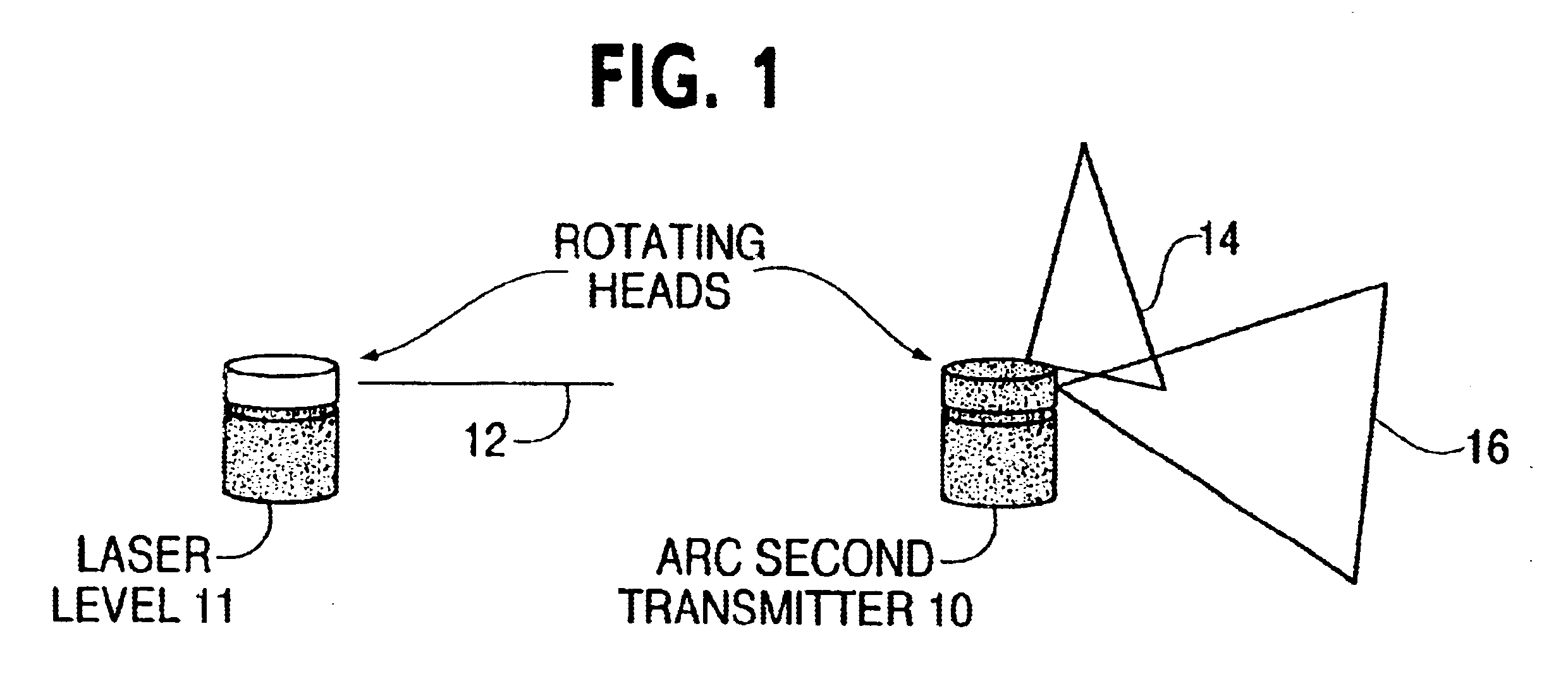
As shown in FIG. 3, a transmitter (10) of the present invention preferably includes the rotating head (7) and synchronization or reference signal emission assembly (6) as described above. A motor drive assembly (5) drives the rotating head (7).

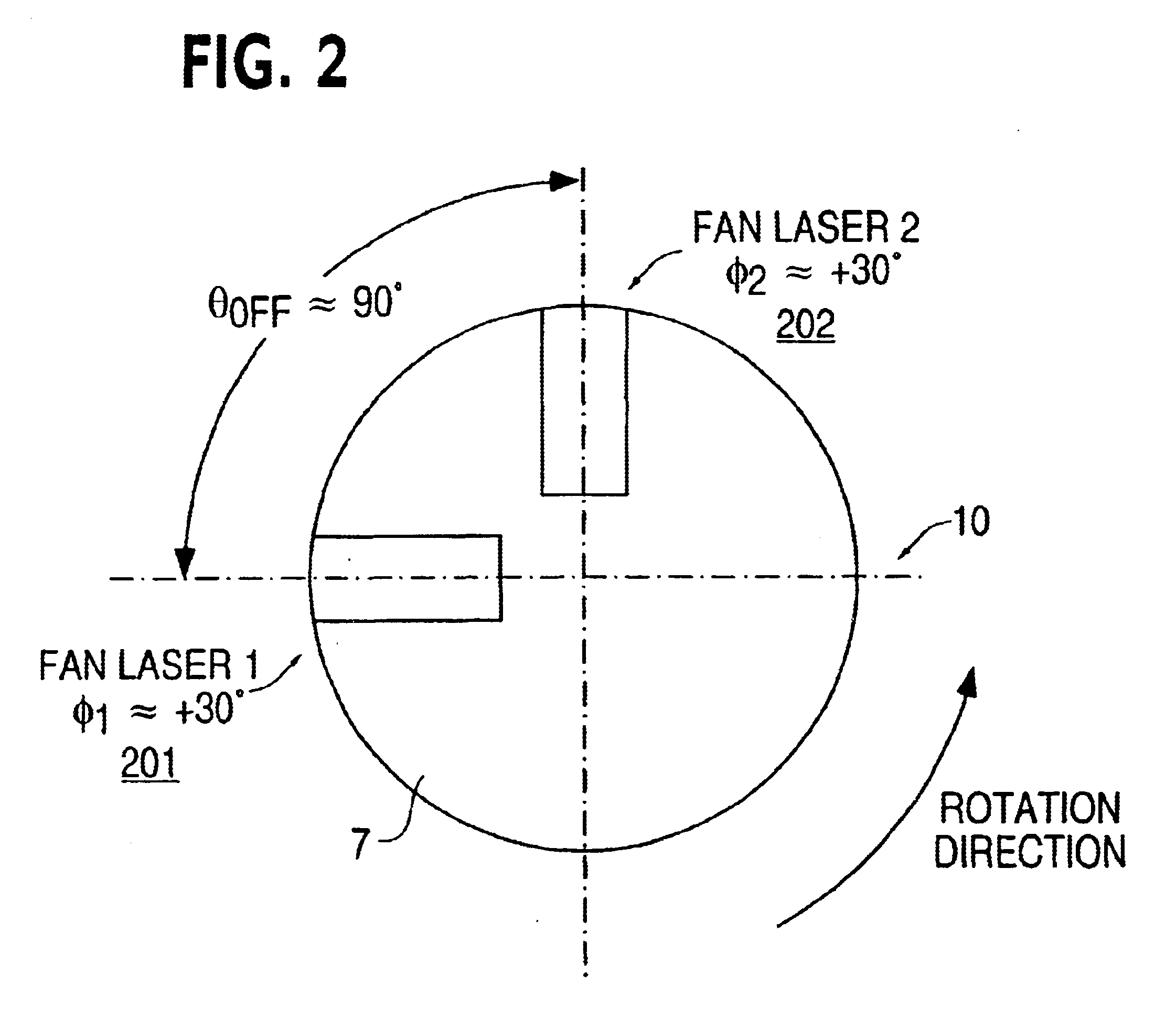
As noted above, the speed of the rotating head is used by the receiver (24) to recognize the transmitter emitting a particular pair of fan beams (14 & 16). Therefore, a motor velocity control circuit (4) is provided to provide power to and regulate the velocity of the motor drive assembly (5).

As described above, in order to achieve a low cost optical transmitter (10) and method, the present invention preferably relies on a calibration procedure p...


PUM


Abstract

Positions can be precisely and accurately fixed instantaneously within a three-dimensional workspace. A system of two or more transmitters each continuously sweep the workspace with two fanned laser beams which are preferably about 90 degrees apart on the rotational axis of the transmitter. A receiving instrument includes, preferably, two light detectors which detect the time at which each fanned laser beam is incident thereon. The light detectors also detect a synchronization pulse from each transmitter that is emitted once per revolution. Beams from different transmitters are differentiated by different rotational speeds and, therefore, different beam incidence cycles. Because three intersecting planes uniquely define a point in three-dimensional space, by detecting at least three of the fan beams from the transmitters, the receiving instrument can calculate its position in the workspace. A Quick Calc setup procedure allows the use to define a desired coordinate system within the workspace.

Description

1. Field of the InventionThis invention relates in general to the field of precise position measurement in a three-dimensional workspace and more particularly to an improved apparatus and method of providing position-related information.2. Description of Related ArtA variety of endeavors require or are greatly aided by the ability to make a precise determination of position within a three-dimensional workspace. For example, laying out a construction site according to a blueprint requires the identification at the actual construction site of a number of actual positions that correspond to features of the building on the blueprint.Despite the many applications which require or are advanced by the ability to make precise determinations of position, it has historically been relatively difficult or expensive to precisely fix the position of any given point relative to an origin in an actual three-dimensional workspace.A variety of techniques are known in the art to measure position, incl...

Claims


Application Information

Patent Timeline
Patent Type & Authority Patents(United States)
IPC IPC(8): G01C15/00G01S1/54G01S1/70G01S1/00G01S5/16G01S5/00G06Q10/00G01B11/00G01S17/88G06Q10/08
CPCG01C15/002G01S1/54G06Q10/08G01S5/16G01S1/70
Inventor HEDGES, THOMAS M.CASTEEL, SCOTT C.DORNBUSCH, ANDREWGAFF, DOUGPENDLETON, EDMUND S.SOBEL, MICHAEL J.WAIN, FREY
Owner ARC SECOND
Why Eureka
Try Eureka