

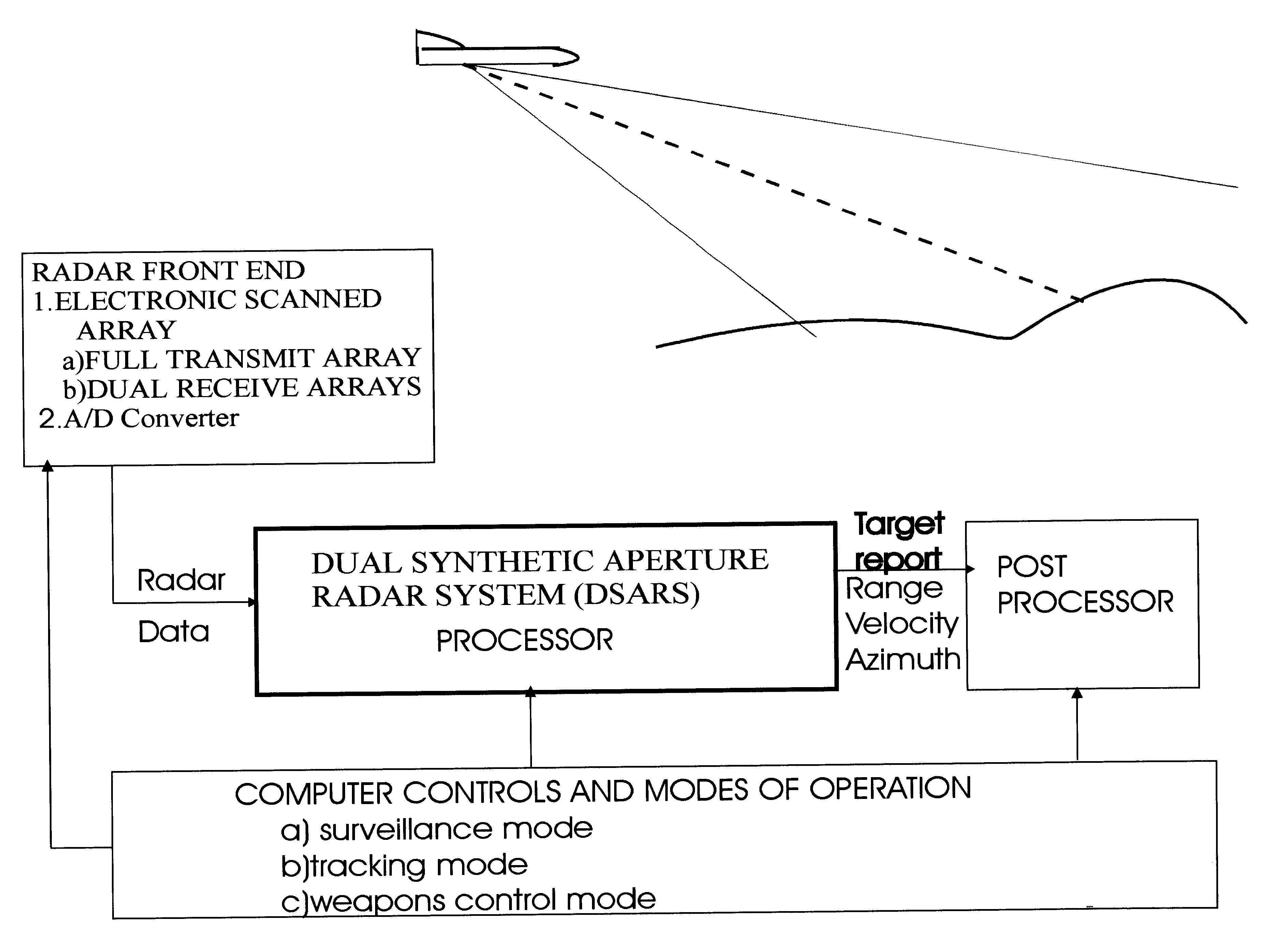
Dual synthetic aperture radar system
a radar system and synthetic aperture technology, applied in the field of synthetic aperture radar systems, can solve the problems of limited accuracy, and achieve the effect of accurate range, cost-effectiveness, and relative radial velocity and angular position of targets
- Summary
- Abstract
- Description
- Claims
- Application Information
AI Technical Summary
Benefits of technology
Problems solved by technology
Method used
Image

Examples
examples
Parameters
Transmission frequency (XF1) of 1.sup.st aperture--1000 MHz-.lambda..sub.1 =0.1.sup.1
Transmission frequency (XF2) of 2.sup.nd aperture--1100 MHz-.lambda..sub.2 =0.909.sup.1
PRF of 1.sup.st aperture--1000 Hz
PRF of 2.sup.nd aperture--1000 Hz
64 Data Points
Same--all other conditions of Radar
Basic Computed Values
Resolution of filter or phase shift per filter 360.degree. / 64=5.625.degree.
Frequency resolution per filter=1000 Hz / 64=15.625 Hz
Ambiguous velocity at XF1-.lambda..sub.1 2.times.PRF=48 feet / second
Ambiguous velocity at XF2-.lambda..sub.2 / 2.times.PRF=43.2 feet / second
Velocity resolution per filter at XF1=48 / 64=0.75 feet / second
Velocity resolution per filter at XF2=43.2 / 64=0.675 feet / second
Unambiguous velocity=(48.times.43.2) / (48-43.2)=432 feet / sec=260 mile / hr
Q-DPCA=14.5.degree. only dependent on PRF=1000 Hz
P-DPCA=2.8.degree. only dependent on PRF=1000 Hz
As seen from the example how the values change. From these parameters and computed values the analogous processing is involv...
PUM
 Abstract
Description
Claims
Application Information