Lubrication structure in OHC engine

a technology of lubrication structure and ohc engine, which is applied in the direction of machine/engine, auxilary lubrication, crankcase compression engine lubrication, etc., can solve the problems of insufficient oil supply to the member that is positioned on the tensioned side of the timing belt, difficulty in splashing oil,

Inactive Publication Date: 2003-10-28
HONDA MOTOR CO LTD
View PDF7 Cites 7 Cited by
  • Summary
  • Abstract
  • Description
  • Claims
  • Application Information

AI Technical Summary

Benefits of technology

Furthermore, in accordance with a second aspect of the present invention, there is proposed a lubrication system in an OHC engine, wherein the valve operation system further includes intake side and exhaust side rocker arms cooperatively connected to the corresponding intake valve and exhaust valve and individually in sliding contact with the lower part of the valve-operating cam at positions on opposite sides of, and an equal distance from, a vertical line passing through the rotational axis of the valve-operating cam coaxially and integrally formed with the driven wheel. A pair of the oil splashing ribs are placed outside a pair of vertical lines, in a projection on a vertical plane that is orthogonal to the rotational axis of the valve-operating cam, that pass through the parts of the rocker arms that are in sliding contact with the valve-operating cam. In accordance with the arrangement, the oil that has collided with the pair of oil splashing ribs can reliably reach the sections where the intake side and exhaust side rocker arms slide on the valve-operating cam. Reliable lubrication of the valve operation system can thereby be carried out by means of a small number of oil splashing ribs.
Furthermore, in accordance with a third aspect of the present invention, there is proposed an OHC engine wherein each of the oil splashing ribs is provided integrally with the curved cover part extending in a direction orthogonal to the rotational direction of the driven wheel. In accordance with the above-mentioned arrangement, the oil can collide with the oil splashing ribs at right angles, and the oil can thereby be splashed more finely.

Problems solved by technology

Even in accordance with the lubrication structure of Japanese Patent Application Laid-open No. 9-151720, it is difficult to splash the oil uniformly within the valve operation chamber, and there is a possibility that, among the members forming the valve operation system, oil supply to the member that is positioned on the tensioned side of the timing belt might become insufficient.

Method used


Image

  • Lubrication structure in OHC engine
  • Lubrication structure in OHC engine
  • Lubrication structure in OHC engine

Examples


Embodiment Construction

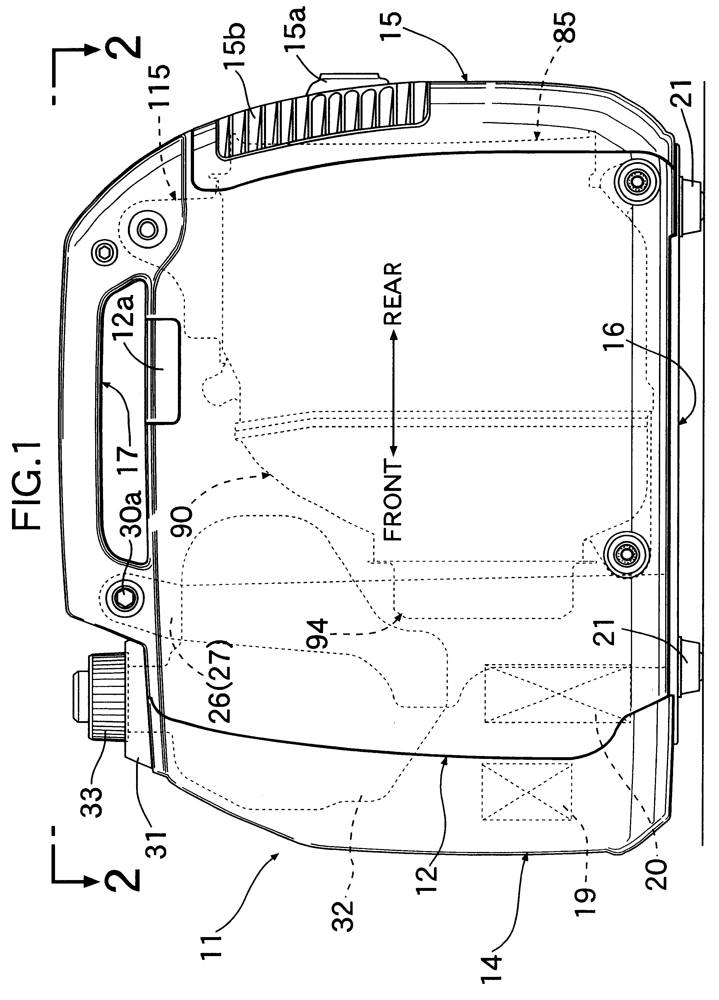
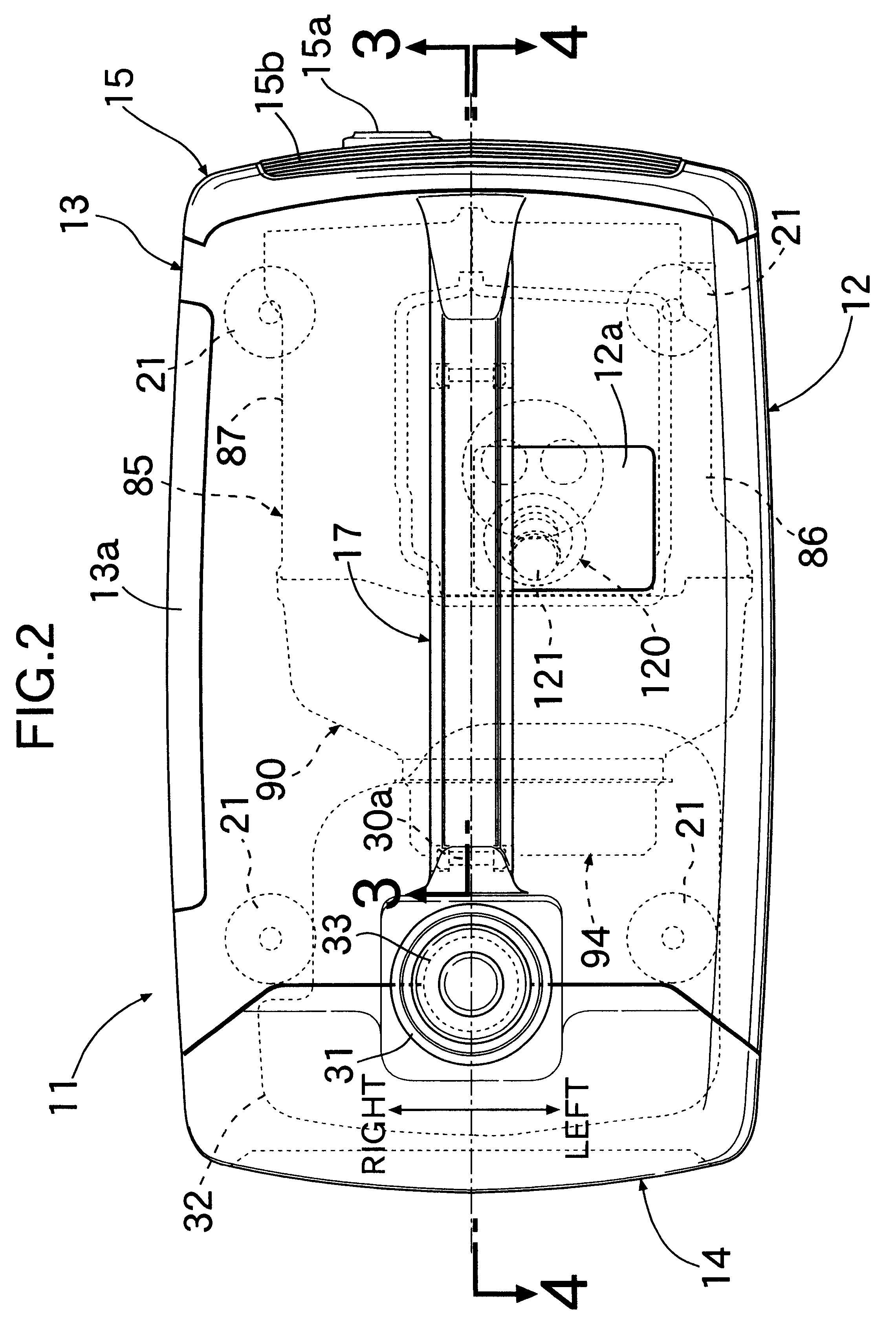
One embodiment of the present invention is explained below by reference to FIGS. 1 to 14. Referring to FIGS. 1 to 4, a synthetic resin case 11 forms an outer shell of a portable engine generator, which is a portable engine-operated machine. The case 11 is formed from a left side cover 12, a right side cover 13, a front cover 14, a rear cover 15 and a under cover 16, which are joined to each other. Provided on the upper parts of the left and right side covers 12 and 13 is a carrying handle 17 for carrying the engine generator. Radial reinforcing ribs 17a are formed within the carrying handle 17 as shown in FIG. 4.

The left side cover 12 is provided with a lid 12a, which can be opened and closed, for replacing a spark plug. The right side cover 13 is provided with a lid 13a, which can be opened and closed, for maintenance. The front cover 14 is provided with a control panel 18. Provided on the inside face of the control panel 18 is a control unit 19 for controlling the operation of an ...


PUM


Abstract

An OHC engine includes a valve operation system housed in a valve operation chamber formed between a cylinder head and a head cover joined to the cylinder head. The valve operation system includes a valve-operating cam and is cooperatively connected to an intake valve and an exhaust valve. The OHC engine also includes timing transmitting device disposed between the valve operation system and a crankshaft, the timing transmitting means including a driven wheel that rotates together with the valve-operating cam and a transmission belt that is wrapped around the driven wheel so that oil within a crankcase can accompany the transmission belt and be supplied to the valve operation chamber. The head cover is provided with an arc-form curved cover part for covering the upper part of the driven wheel. The curved cover part integrally includes above the driven wheel a plurality of oil splashing ribs that are positioned at intervals along the rotational direction of the driven wheel to project toward the side that is closer to the transmission belt, thereby allowing oil to be supplied uniformly to each section of the valve operation system.

Description

1. Field of the InventionThe present invention relates to an OHC engine in which a valve operation system is housed in a valve operation chamber formed between a cylinder head and a head cover joined to the cylinder head. The valve operation system includes a valve-operating cam that is rotatably supported by the cylinder head and is cooperatively connected to an intake valve and an exhaust valve; and timing transmitting means disposed between the valve operation system and a crankshaft. The timing transmitting means includes a driven wheel that rotates together with the valve-operating cam and a transmission belt that is wrapped around the driven wheel, so that oil within a crankcase is carried by the transmission belt and is supplied to the valve operation chamber. In particular, it relates to an improvement of a lubrication structure for the valve operation system.2. Description of the Prior ArtA conventional lubrication structure for an OHC engine is already known in, for exampl...

Claims


Application Information

Patent Timeline
Patent Type & Authority Patents(United States)
IPC IPC(8): F01M9/00F01M9/10F02B75/16F02B75/00F02F7/00F02B63/04F02B63/00F01M9/06
CPCF01M9/10F02B63/04F02F7/006F02B75/16F02B2063/046F01L1/182F01L1/20F01L2001/0535
Inventor SATO, YOSHIKAZUKATAYAMA, SHINJI
Owner HONDA MOTOR CO LTD
Why Eureka
Try Eureka