Driving device for synchronous motor

a technology of synchronous motors and driving devices, which is applied in the direction of motor/generator/converter stoppers, dynamo-electric gear control, and dynamo-electric converter control. it can solve the problems of generating transient vibration, and avoiding the use of synchronous motors

Inactive Publication Date: 2003-10-28
HITACHI IND EQUIP SYST CO LTD
View PDF10 Cites 52 Cited by
  • Summary
  • Abstract
  • Description
  • Claims
  • Application Information

AI Technical Summary

Problems solved by technology

However, if a load changes abruptly while driving, it may generate a transient vibration.
However, since an actual calculation for the estimation is affected by a parameter fluctuation of a motor, or a delay in the calculation, accuracy comparable to that of a position or a speed sensor is not attained, and an estimation error always accompanies.
However, an axial error exists in reality, and the vector control type sensorless method does not attain a sufficient capability for the speed control or the current control, and adjusting the control gains for them becomes difficult.
When an unstable phenomenon arises

Method used


Image

  • Driving device for synchronous motor
  • Driving device for synchronous motor
  • Driving device for synchronous motor

Examples


embodiment 1

(Embodiment 1)

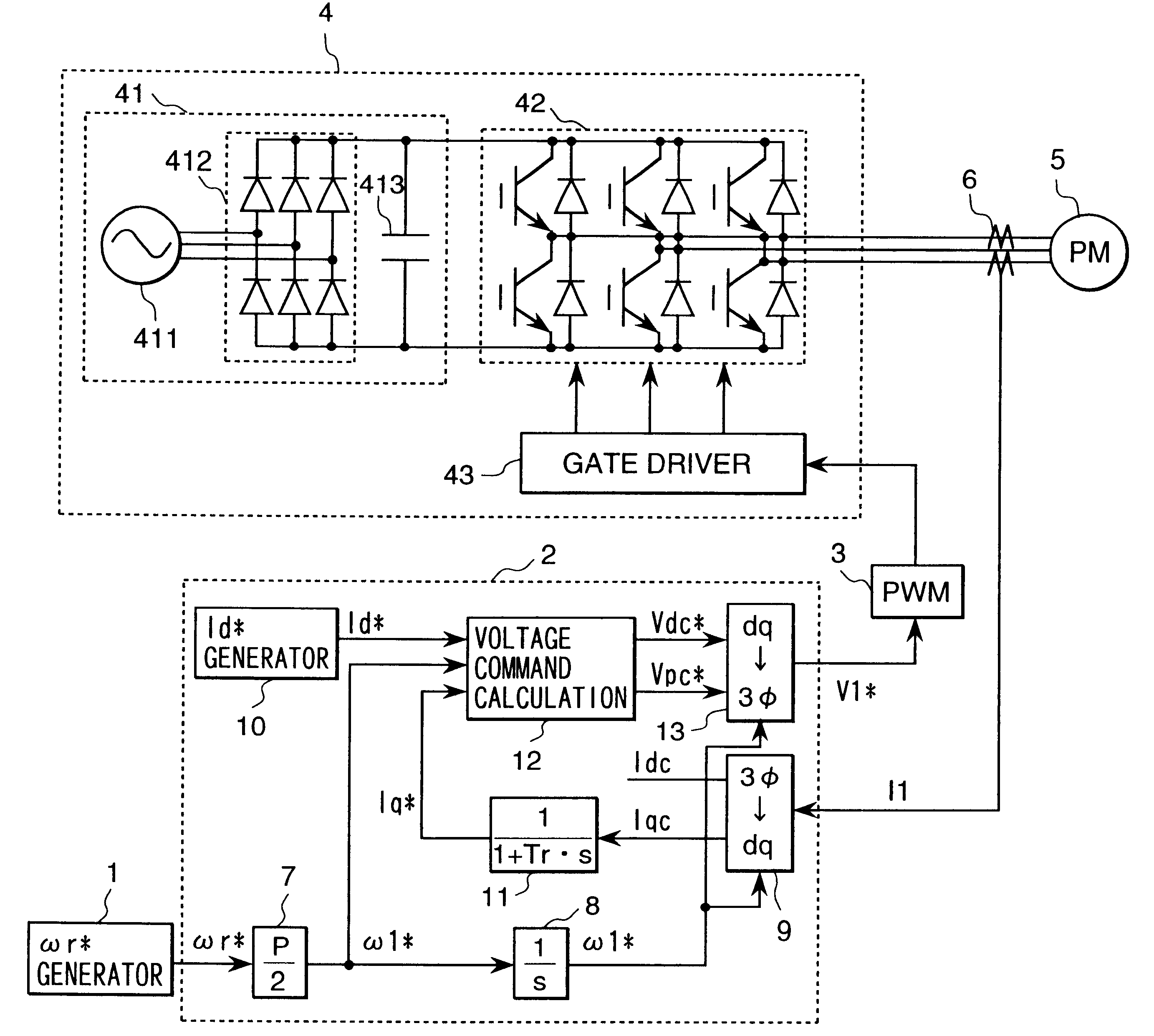
FIG. 1 shows a constitution of the present embodiment. In FIG. 1, 1 is a speed command generator providing a motor with a rotation speed command .omega.r*, 2 is a controlling device calculating a voltage impressed on the motor, 3 is a PWM (Pulse Width Modulation) pulse generator generating pulses driving an inverter 4 based on a voltage command V1*, 4 is the inverter driving the motor, 5 is the synchronous motor (referred as motor hereafter) as a control subject, 6 is a current detector detecting the current of the motor 5, 7 is a conversion gain converting the rotation speed command .omega.r* into an electric angular frequency command .omega.1* of the motor (P is the number of poles of the motor), 8 is an integrator calculating an AC phase .theta.c inside the controlling device based on the electric angular frequency command .omega.1*, 9 is a dq coordinate converter converting a current value on a three-phase AC axis to components on dc / qc axes, which are rotation coo...

embodiment 2

(Embodiment 2)

In the present embodiment, a controlling device 2B in FIG. 4 is used in place of the controlling device 2 in FIG. 1. In FIG. 4, 14 is an axis error estimator estimating and calculating an axis error between d / q axes of the motor and dc / qc axes of the control axes. 15 is a zero generator providing the axis error with a zero command. 16 is an adder adding (or subtracting) input signals. 17 is a magnetic pole estimation gain calculating a correction value for the electric angular frequency command .omega.1* using the axis error.

The following section describes the operation of the present embodiment. The axis error estimator 14 estimates and calculates an error .DELTA..theta. between d / q axes and the dc / qc axes. .DELTA..theta. is an error component of the dc / qc axes observed from d / q axes as indicated in FIG. 23. .DELTA..theta.c, which is an estimated value of .DELTA..theta., is calculated with Equation (3). ##EQU2##

In the equation above, L=Ld=lq and a non-salient type mot...

embodiment 3

(Embodiment 3)

In the present embodiment, a controlling device 2C in FIG. 5 is used in place of the controlling device 2 in Embodiment 1. 18 is a torque controller calculating the q axis current command Iq* based on the estimated value of the axis error .DELTA..theta.c in FIG. 5. The difference of the present embodiment from Embodiment 2 is that the Iq* generator 11 is removed, and a torque controller 18 is added.

The following section describes the operation of the present embodiment. The present embodiment determines the current command Iq* using the estimated value for the axis error .DELTA..theta.c. The phase .theta.c of AC voltage impressed on the motor is mainly given by integrating the electric angular frequency .omega.1*. When a load changes suddenly, the estimated value for the axis error .DELTA..theta.c changes first. Though the electric angular frequency .omega.1* is corrected through the magnetic pole estimation gain 17, it takes a period corresponding to a response set fo...


PUM


Abstract

In order to provide a driving device for a motor having a capability equivalent to conventional vector control type sensorless method by simplifying the controls structure to reduce number of parts to be adjusted, and to stabilize the control system, a driving device for a synchronous motor does not include a speed controller or a current controller, and calculates a voltage impressed on a motor on coordinate axes (dc/qc axes) based on a magnetic pole axis. For calculating a voltage command, command values such as a rotation speed command and a current command are used, and Iq* corresponding to a torque current command is calculated and provided based on a detected current value.

Description

1. Field of the InventionThe present invention relates to control of a synchronous motor, and especially relates to a control method for realizing a high precision and high performance driving device for a motor without sensors detecting the speed and the position of the motor.2. Prior ArtThe prior art for controlling a synchronous motor without detecting a magnetic pole position includes vector control type sensorless method which is based on vector control with speed and position sensors of a synchronous motor, and is provided with a magnetic pole position estimator 14P and a speed estimator 33 instead of using the speed and position sensors as shown in FIG. 21, and a method called V / F control for controlling a synchronous motor as an open loop shown in FIG. 22.In the vector control type sensorless method shown in FIG. 21, the other part than a part for detecting magnetic pole position and a part for detecting speed is constituted as in vector control method with sensors.In FIG. 2...

Claims


Application Information

Patent Timeline
IPC IPC(8): H02P6/08H02P6/06H02P6/16H02P6/18H02P6/28H02P21/00H02P21/14H02P21/16H02P21/18H02P21/22H02P21/24H02P21/34H02P23/14H02P23/16H02P23/18H02P25/026H02P27/04H02P27/08
CPCH02P6/085H02P21/14H02P21/0039H02P21/0003H02P21/24
Inventor IWAJI, YOSHITAKAENDO, TSUNEHIROYAMADA, NORIAKIFUJII, HIROSHISAKAMOTO, KIYOSHI
Owner HITACHI IND EQUIP SYST CO LTD
Why Eureka
Try Eureka