Electronic dimming ballast for compact fluorescent lamps

a technology of compact fluorescent lamps and ballasts, which is applied in the direction of electric discharge lamps, energy-saving lighting, sustainable buildings, etc., can solve the problems of compact fluorescent lamps, in comparison, and additional lamp instability areas of compact fluorescent lamps

Inactive Publication Date: 2003-11-04
LUTRON TECH CO LLC
View PDF5 Cites 47 Cited by
  • Summary
  • Abstract
  • Description
  • Claims
  • Application Information

AI Technical Summary

Benefits of technology

According to aspects of the invention, the frequency of operation of the inverter circuit is determined by a control circuit comprising a frequency-determining resistor-capacitor (RC) network. The component values of the RC network ...

Problems solved by technology

Operation of the lamp is inherently unstable, due to this negative incremental impedance characteristic, and thus the current between the electrodes must be controlled to provide stable operation of the lamp.
In addition, the inventors have discovered that compact fluorescent lamps, in comparison to typical linear fluorescent lamps, h...

Method used


Image

  • Electronic dimming ballast for compact fluorescent lamps
  • Electronic dimming ballast for compact fluorescent lamps
  • Electronic dimming ballast for compact fluorescent lamps

Examples


Embodiment Construction

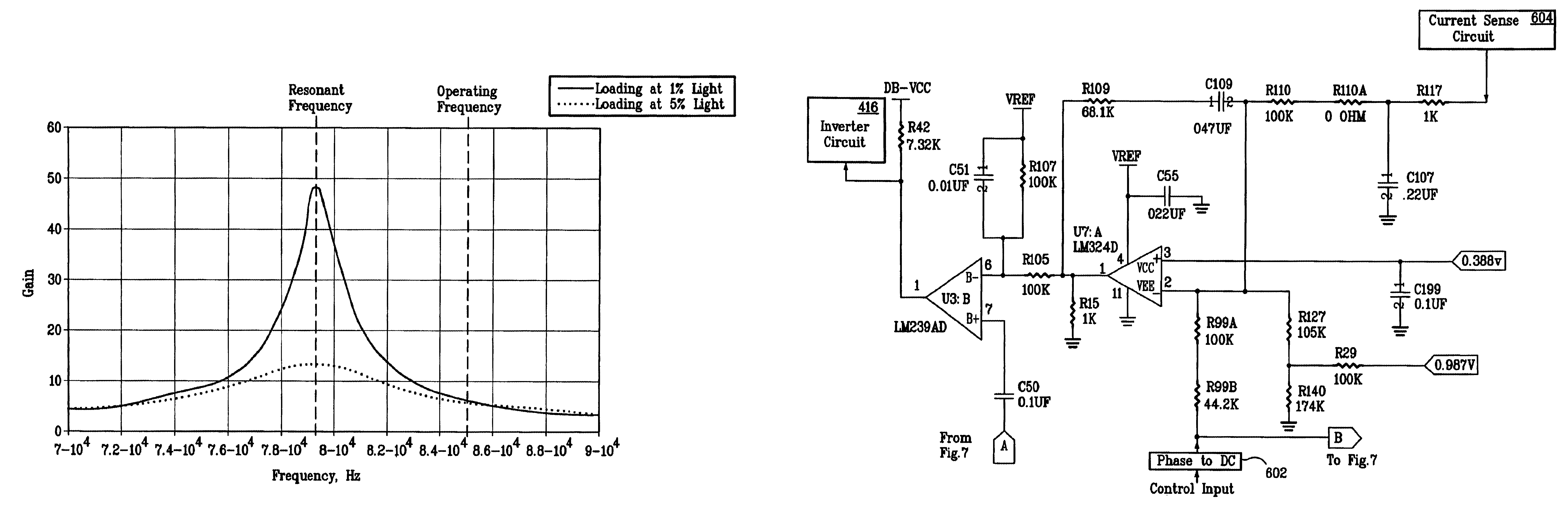
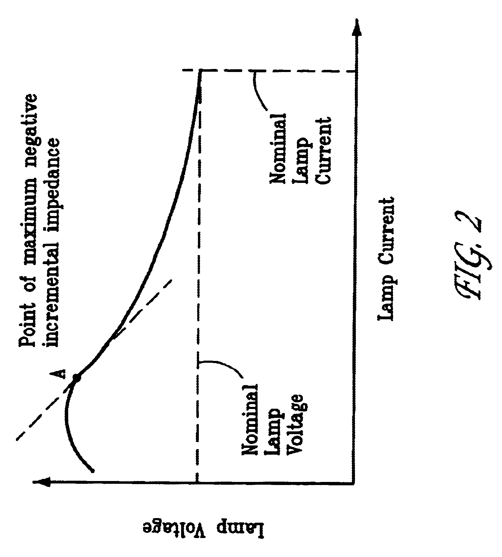
Lamp light output stability is generally related to the quality of the current source used to operate the lamp. Current source quality is described numerically by a quantity called its output impedance. Output impedance is defined as the ratio of the change in RMS output voltage divided by the corresponding change in RMS output current, and has the units of ohms. Therefore, a current source which exhibits a change in current level of 0.001 amperes as a result of a change in output voltage of one volt would have an output impedance of one volt divided by 0.001 amperes or 1,000 ohms.

FIG. 2 is a plot of the voltage / current characteristic of a typical fluorescent lamp. The lamp incremental impedance at any operating point on this curve is defined as the slope of the curve at that point. From this, one can see that the lamp incremental impedance is positive at very low currents, then becomes zero at a maximum voltage point, and goes rapidly negative as current increases still further. ...


PUM


Abstract

The operating frequency of a ballast is sufficiently far from resonance that, when a compact fluorescent lamp is dimmed to about one percent light output level, the ballast is operating with an open loop gain below a predetermined level, such as, for example, 15, and is operating with an output impedance greater than a predetermined level, such as, for example, the absolute value of the maximum negative incremental impedance of the lamp, and more preferably, greater than twice the absolute value of the maximum negative incremental impedance of the lamp. By changing the frequency to 85 kHz from 80 kHz, for example, the gain is maintained about the same whether the light output is at five percent or one percent, for example. This provides a stable control loop. In this manner, compact fluorescent lamps can be dimmed below about one percent light output, without dropping out and without observable flicker.

Description

The present invention relates in general to dimming gas discharge lamps and, more particularly, to electronic dimming ballasts for dimming compact fluorescent lamps.A gas discharge lamp converts electrical energy into visible light with high efficiency. A gas discharge lamp is generally an elongated gas-filled (usually low-pressure mercury vapor) tube having electrodes at each end. Each electrode is typically formed from a resistive filament (usually tungsten) coated with a thermionically emissive material, such as a mixture of alkaline earth oxides.The steady-state operation of a typical gas discharge lamp is as follows. Voltage is applied across the resistive filaments, heating the electrodes to a temperature sufficient to cause thermionic emission of electrons into the discharge tube. A voltage applied between the electrodes accelerates the electrons toward the anode. En route to the anode, the electrons collide with gas atoms to produce positive ions and additional electrons, fo...

Claims


Application Information

Patent Timeline
IPC IPC(8): H05B41/39H05B41/392H05B41/24
CPCH05B41/3921H05B41/3925Y10S315/04Y02B20/19Y02B20/00
Inventor MACADAM, RUSSELL L.OFFENBACHER, ANDREW RYANARAKKAL, JECKO J.
Owner LUTRON TECH CO LLC
Why Eureka
Try Eureka