Method, apparatus and support for testing poles

a technology of apparatus and support, applied in the direction of lifting frames, lifting devices, and material strength using steady bending forces, can solve the problems of insufficient support ability of existing profiles, high manufacturing cost of supports, and large weight of cables, and achieve the effect of sharp edges

Inactive Publication Date: 2003-11-18
DEUAR ANNA TERESA
View PDF17 Cites 23 Cited by
  • Summary
  • Abstract
  • Description
  • Claims
  • Application Information

AI Technical Summary

Benefits of technology

The width of the longitudinal end plates can vary depending on the degree of support required and the size of the pole. For instance, increasing the width of the end plates will increase the stiffness of the pole support and therefore the ability of the support to withstand forces applied to it. Increasing the thickness of the end plates will also achieve a similar result.
The spacing between the end plates will vary depending on the diameter or cross-sectional size of the pole. As most power poles are between to 50 cm in diameter, it is preferred that the end plates are similarly spaced apart such that the ground pole can pass at least partially between the end plates. For reasons of safety, it is preferred that there is minimal gap between the end plate and the outer surface of the pole which could snag fingers of passers by or become a collection point for dirt and debris which may reduce the effective life of the pole.
For reasons of strength and improved use, it is preferred that the end plates are plate-like which present longitudinal edges which are approximately at right angles and therefore present a quite sharp hard steel edge which can cause injury.
For this reason, another form of the invention includes a means by which the sharp edge can be eliminated or at least reduced to provide a pole support having suitable safety characteristics.

Problems solved by technology

For some poles, the weight of these cables can be quite considerable and some poles contain additional devices such as power transformers which are quite heavy.
A disadvantage with these types of pole supports is that the required profile is complex and makes the supports expensive to manufacture.
Also, existing profiles are not entirely satisfactory in their supporting ability.
Wood rot, bores, termites and other factors operate to reduce the strength, and therefore, the service life of poles.
As wood rot generally occurs below the ground level, a simple visual inspection is not sufficient and mechanical strength tests must be carried out.
To date, no simple, efficient and reliable test method has been available so poles are often replaced well before the end of their effective life.
This naturally increases the operating expenses of the electricity authority.

Method used


Image

  • Method, apparatus and support for testing poles
  • Method, apparatus and support for testing poles
  • Method, apparatus and support for testing poles

Examples


Embodiment Construction

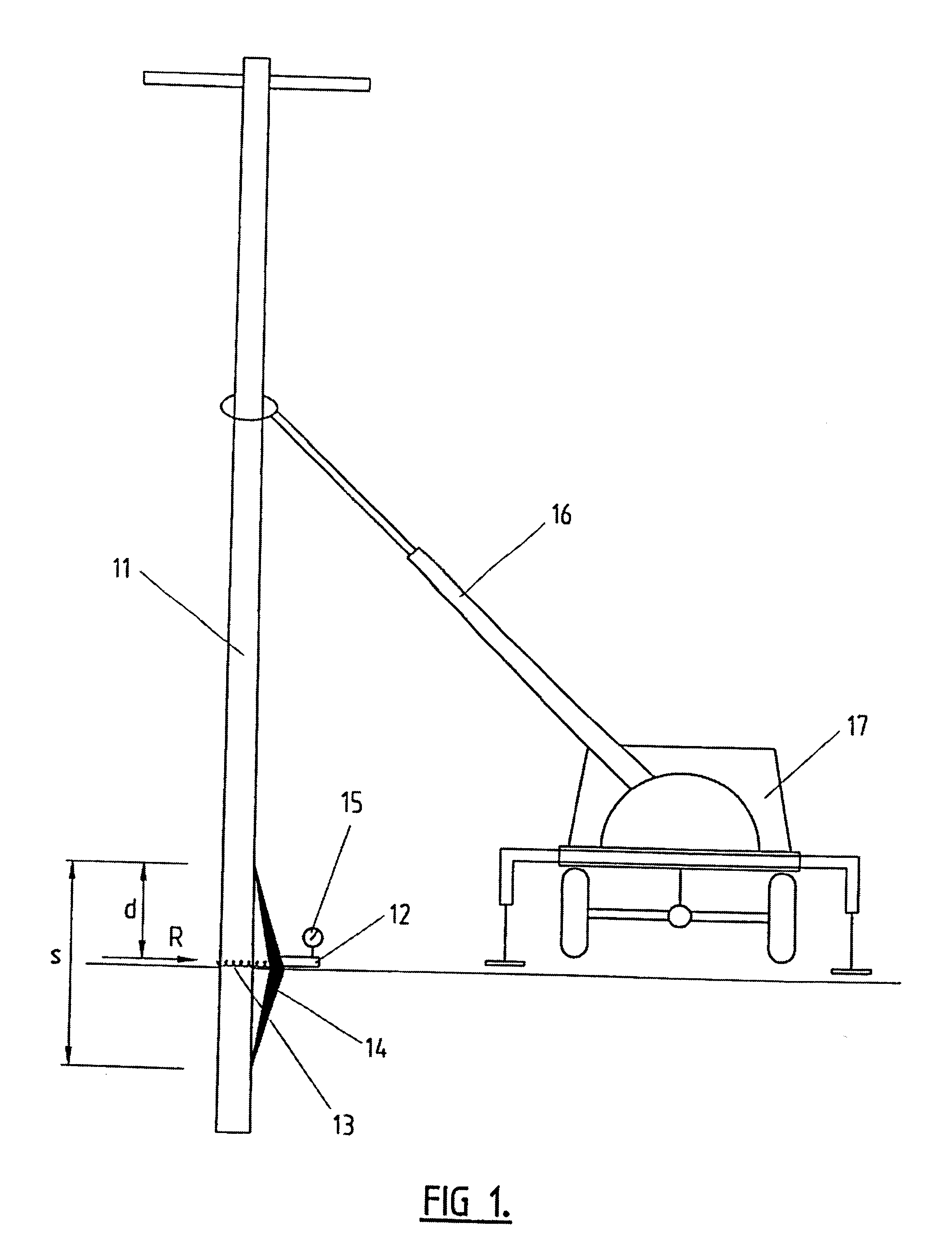
Referring to FIG. 1, a pole 11 is pulled with a hydraulic ram 12 through a chain 13 and simultaneously pushed with the ends of a beam 14 until a preset load R is obtained on a load cell 15.

The beam 14 can be operated by a crane boom 16 mounted on a truck 17.

Having the values of the predetermined required strength of pole M, the span s of the beam 14 and the distance d between the hydraulic ram 12 and one of the ends of the beam, the load R to be obtained on the load cell can be easily calculated from the following formula: ##EQU1##

Stability of the pole in case of its failure is provided by a safety boom 16 of a truck 17, or by a pole support illustrated in FIGS. 7 to 15.

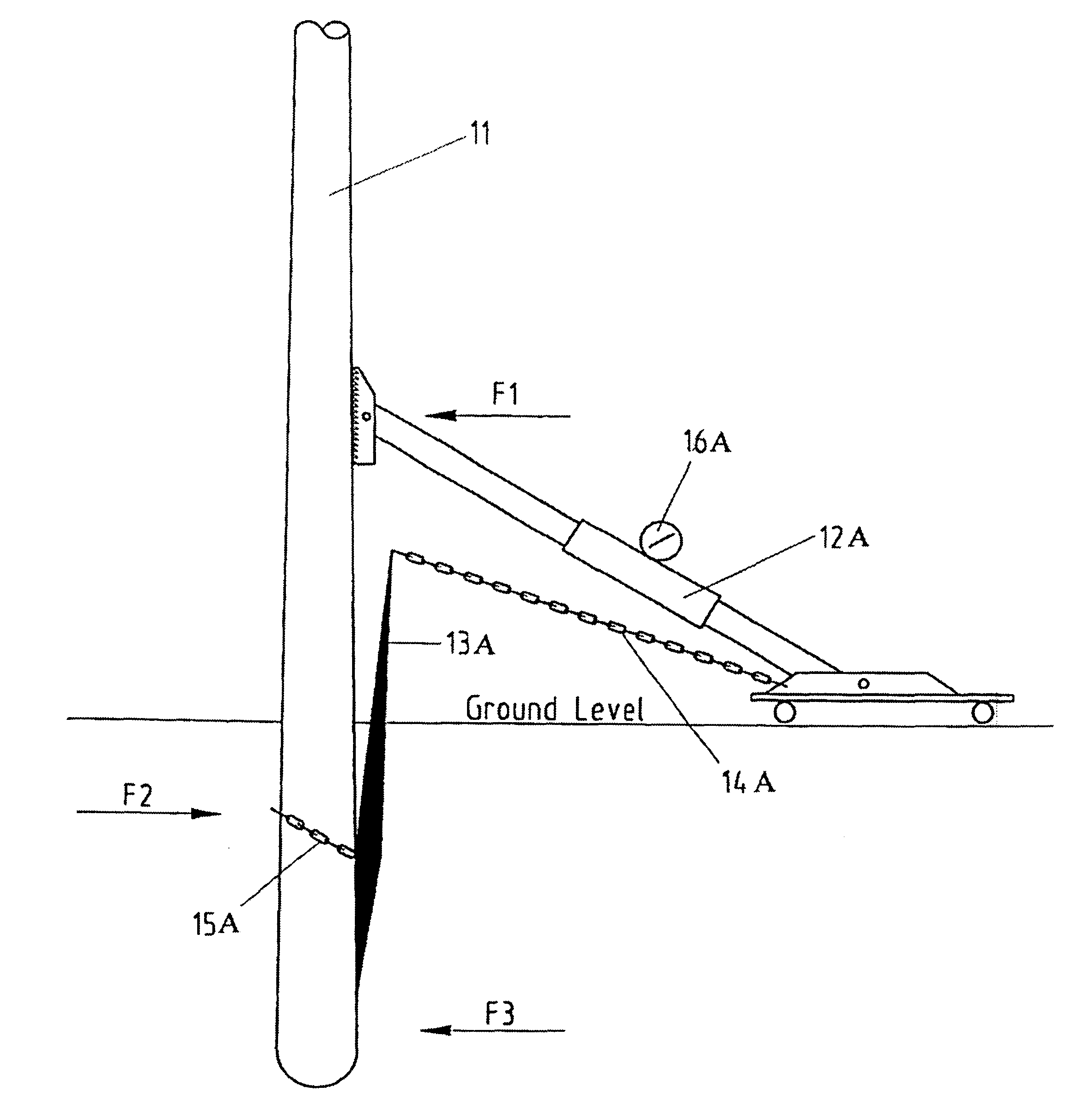
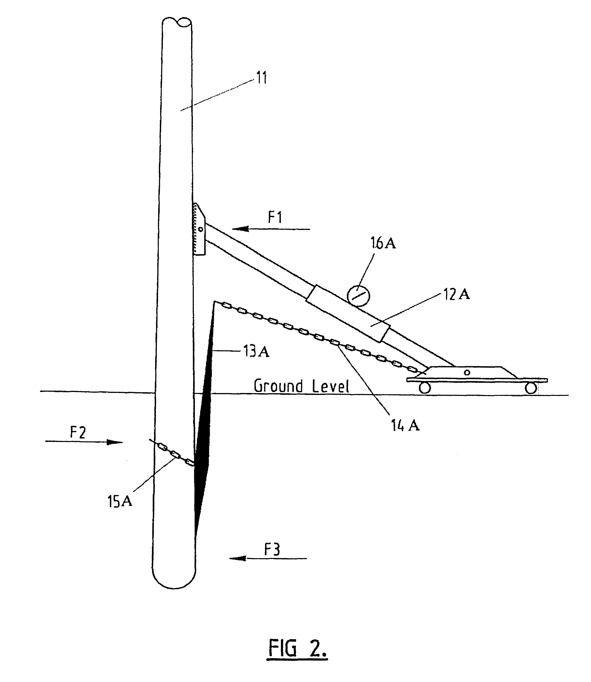
Referring to FIG. 2, a pole 11 is simultaneously:

pushed with a hydraulic ram 12 which by its extension pulls the top end of a vertical beam 13 through a chain 14, and

pulled with a chain which is attached to the lower part of the vertical beam 13, and

pushed with the bottom end of the vertical beam 13 below the ground ...


PUM

PropertyMeasurementUnit
lengthaaaaaaaaaa
distanceaaaaaaaaaa
lengthsaaaaaaaaaa

Abstract

A pole support for ground poles, such as telephone poles and power poles, is disclosed. The support can be driven into the ground next to the pole. It has a pair of spaced apart longitudinal end plates which are interconnected intermediate their ends by an intermediate plate. The end plates are spaced apart to allow the ground pole to pass at least partially between the end plates. Each end plate has a front longitudinal edge which, in use, is adjacent to the pole and a rear longitudinal edge which, in use, is directed away from the pole. The pole support has means to reduce sharp edges on the rear longitudinal edges. Also disclosed is a method for testing pole strength which comprises applying a load to the pole and either measuring its displacement or observing if it withstands the load. The amount of load applied to the pole and the degree of displacement is undergoes can be used to calculate the residual strength of the pole.

Description

This invention relates to a method of and apparatus for the testing of poles. Throughout the specification, the term "poles" shall be used to include electricity, telephone and telegraphic poles; fence and retaining wall posts and the like.This invention also relates to a pole support for ground poles and particularly relates to a pole support which can be driven into the ground next to a ground pole to support the pole against leaning or toppling over.Power poles and telephone poles are conventionally formed from wood, steel or concrete and are pounded into the ground, or a hole is drilled into the ground and the pole is inserted into the hole.Once the pole has been put into the ground, the upper part of the pole is arranged to receive power cables, data cables, telephone cables and the like. For some poles, the weight of these cables can be quite considerable and some poles contain additional devices such as power transformers which are quite heavy.Occasionally, the poles need to ...

Claims


Application Information

Patent Timeline
Patent Type & Authority Patents(United States)
IPC IPC(8): E04H12/20E04H12/00E04H12/22G01N3/20G01N3/00G01N33/00
CPCE04H12/20E04H12/2292G01N3/20G01M5/0058G01N2033/0078
Inventor DEUAR, KRZYSZTOF JAN
Owner DEUAR ANNA TERESA
Why Eureka
Try Eureka