
Apparatus for cleaning a coiler furnace drum

a technology for cleaning apparatus and coiler furnace drum, which is applied in the direction of cleaning process, furnace type, furnace, etc., can solve the problems of scale and other debris, the work surface of the coiler furnace drum, and the accumulation of unwanted matter

Inactive Publication Date: 2003-11-18
IPSCO ENTERPRISES
View PDF5 Cites 17 Cited by
  • Summary
  • Abstract
  • Description
  • Claims
  • Application Information

AI Technical Summary

Problems solved by technology

During use, the work surface of the coiler furnace drum (that is, that portion of the coiler furnace drum that contacts the plate or strip) tends to accumulate unwanted matter such as scale and other debris.
This procedure is sometimes ineffective and hazardous, and typically may be performed only when the coiler furnace is idle and (depending on the means for holding the scraper against the drum) relatively cool.
Due to uneven wear along their lengths, known drum cleaners typically do not provide even or consistent contact pressure against the drum, and thus do not provide even or consistent cleaning of the drum.
However, with such a configuration, the insertion / removal apparatus would have to be installed so as to take up space in the production line (where space is typically limited) rather than installed to the side of the production line.
The depth guide may, in use, tend to contact the unwanted matter to be removed from the work surface.
Conceivably, as the depth guide rides over such unwanted matter, the depth guide could cause the carriage to move away from the work surface so as to reduce the cleaning effectiveness of the brush.
From time to time the unwanted matter builds to a sufficient thickness that it does reduce the cleaning effectiveness.

Method used


Image

  • Apparatus for cleaning a coiler furnace drum
  • Apparatus for cleaning a coiler furnace drum
  • Apparatus for cleaning a coiler furnace drum

Examples


Embodiment Construction

In this specification and in the claims, absolute directions such as up and down, and relative descriptive terms associated with absolute directions, such as top, bottom and side, are used for clarity of description and should not be understood as implying that the described embodiments cannot be used in a variety of orientations and relative positions.

Three different embodiments of the coiler drum cleaner of the present invention are described herein. In this description and in the relevant drawings, common components as between the different embodiments of the present invention are identified using common terms and common reference characters.

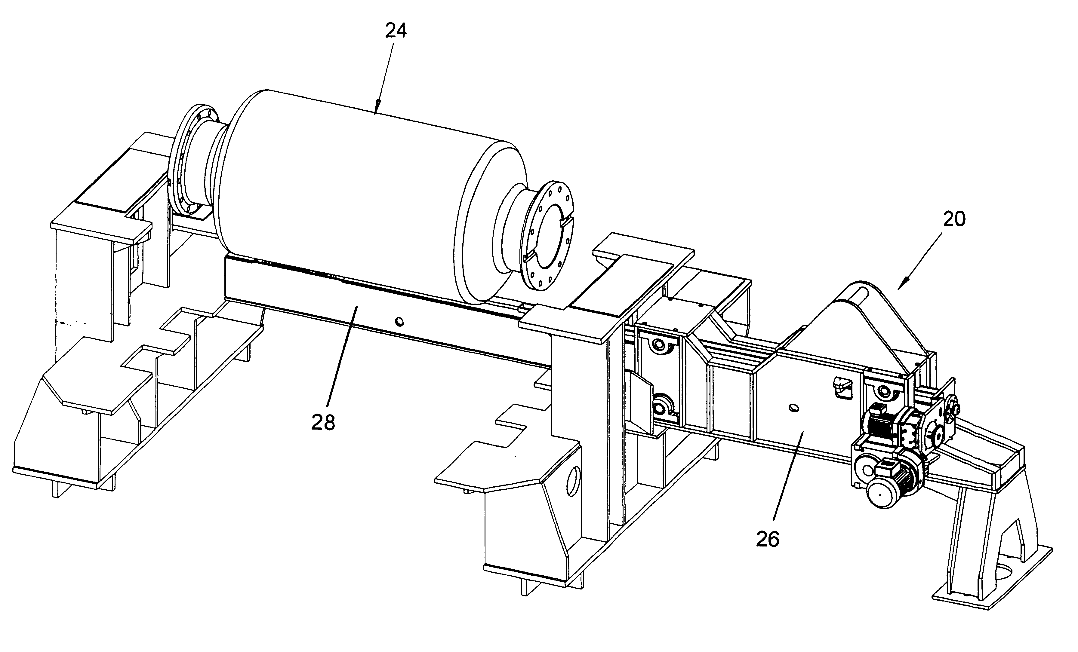
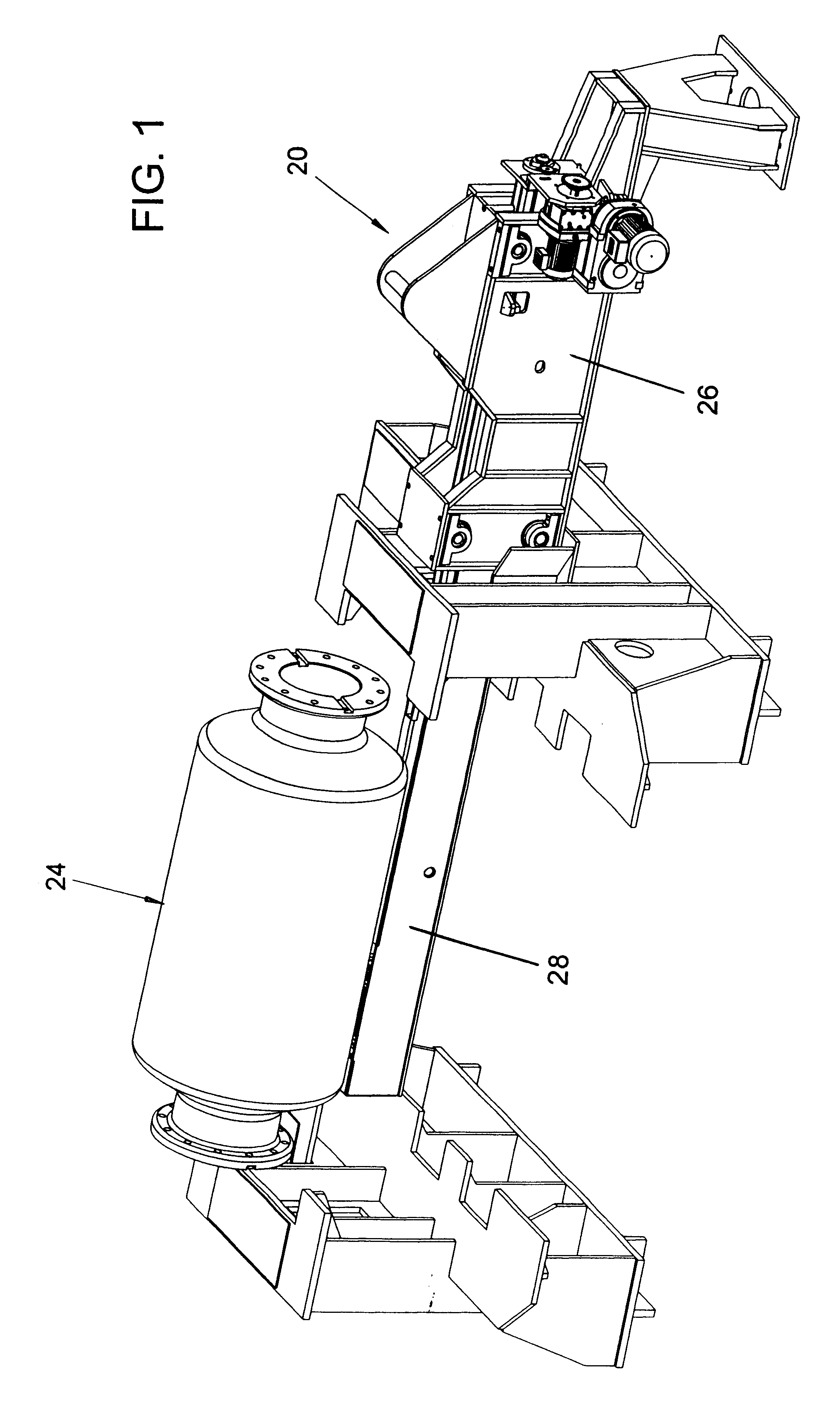
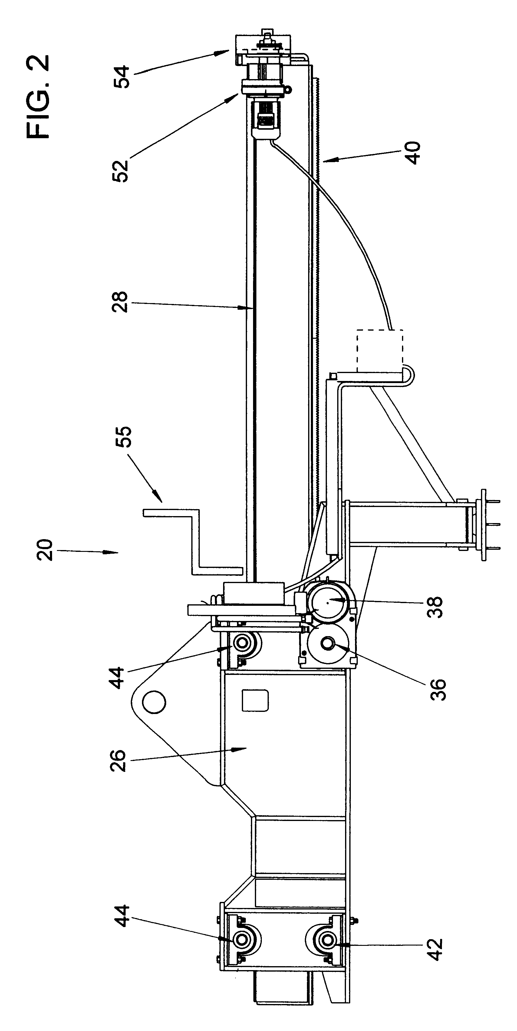
FIG. 1 shows an exemplary single-brush cleaner 20 in association with a coiler drum 24. For clarity, the housing of the coiler furnace (indicated in subsequent drawings with reference number 22) and the drive and support means for the coiler drum 24 are not shown in FIG. 1. The single-brush cleaner 20 includes a cleaner frame 26 and a brush t...


PUM


Abstract

A coiler drum cleaner for cleaning the drum of a coiler furnace (typically associated with a reversing rolling mill or Steckel mill) is disclosed. The coiler drum cleaner includes a cleaning element rotatably mounted at one end of a longitudinally extending tubular member, the tubular member being movably installed in association with a coiler furnace such that the cleaning element may be inserted into the coiler furnace and moved across the surface of the coiler drum, by moving the tubular member substantially parallel to the axis of rotation of the coiler furnace drum. The tubular member also includes means for moving the cleaning element roughly perpendicular to the longitudinal axis of the tubular member so as to bring the cleaning element into contact with the drum. In use, the cleaning element is inserted into the coiler furnace, brought into contact with the coiler drum and rotated so as to clean the coiler drum. Preferably, the cleaning element is a cylindrical brush having a plurality of resiliently-flexible carbide-tipped steel tines arrayed about its circumference. The tubular member may also include cooling means.

Description

The invention relates to a drum cleaner for cleaning a coiler furnace drum such as a drum of the type found in coiler furnaces for use with Steckel mills (reversing rolling mills).BACKGROUND TO THE INVENTIONA Steckel mill is one of the various types of rolling mill commonly installed in a production line for the manufacture of steel plate or strip. A Steckel mill is typically used to roll the steel (so as to reduce the thickness of the steel) while the steel is at a desired (typically relatively high) temperature so as to produce a desired steel microstructure. As such rolling reduction typically requires more than one pass (and sometimes several passes) through the Steckel mill, coiler furnaces are typically installed in line with the Steckel mill (one coiler furnace upstream of the Steckel mill and a second downstream of the Steckel mill) to maintain the temperature of the steel between passes through the Steckel mill. A coiler furnace has an internal rotatable generally-cylindric...

Claims


Application Information

Patent Timeline
IPC IPC(8): B08B1/00B08B1/04B08B9/20B08B9/38B08B9/36F27D23/00F27D23/02F27D25/00
CPCF27D25/001
Inventor SUCHAN, MICHAEL J.BROOKS, RUSSELL J.BANOWETZ, GLEN
Owner IPSCO ENTERPRISES
Learn More