Robot remote controlling apparatus and robot apparatus

a remote control and robot technology, applied in the field of robot equipment, can solve the problems of difficulty in operation, cumbersome attachment and detachment of such devices, and sweating of operators,

Inactive Publication Date: 2003-11-18
TMSUK CO LTD
View PDF5 Cites 7 Cited by
  • Summary
  • Abstract
  • Description
  • Claims
  • Application Information

AI Technical Summary

Benefits of technology

Thereby, it is possible to obtain a robot remote controlling apparatus that can easily and comfortably carry out operations at the finger portion operating portion and arm portion operating portion, and can easily and comfortably carry out operations at other parts than at the above-described portions.
With the above-described construction, such an advantageous effect can brought about, by which the structure of the robot apparatus is simplified, and it becomes possible to handle various types of goods for various uses. Furthermore, the construction can bring about such an advantageous effect of displaying sufficient forces (torque) and number of revolutions since the travelling thereof is driven by an engine. Since the respective parts of the robot are driven by hydraulic pressure, wherein, since no oil pressure is employed, the danger of fire can be excluded even if the hydraulic pressure tube is broken, and if water is colored, it is possible to easily locate the breakage point.

Problems solved by technology

However, since, in a prior art finger portion operating portion, the data glove is shaped to be a glove and it is necessary to attach conductive gel, which acts as sensors, to the joints of respective fingers, there occur some problems in that the attaching and detaching thereof is made cumbersome, and fingers perspire in a glove when it is hot, and the sweating makes an operator uncomfortable.
Also, there occur other problems in that a structure of the prior art arm portion operating portion is such that the man carries the same on his shoulders, and it is heavy to carry the arm portion operating portion, resulting in a difficulty in operation.

Method used


Image

  • Robot remote controlling apparatus and robot apparatus
  • Robot remote controlling apparatus and robot apparatus
  • Robot remote controlling apparatus and robot apparatus

Examples


embodiment 1

(Embodiment 1)

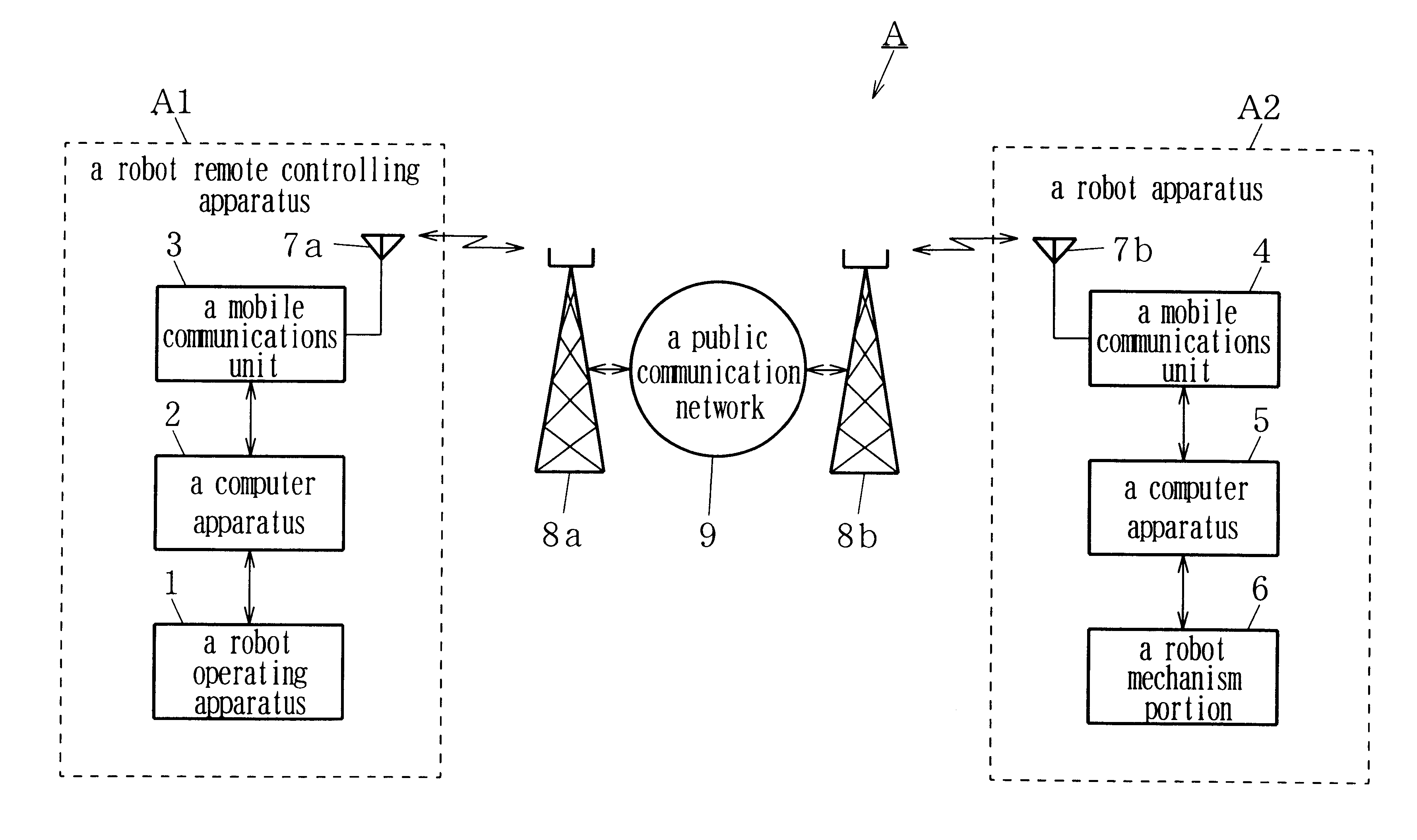
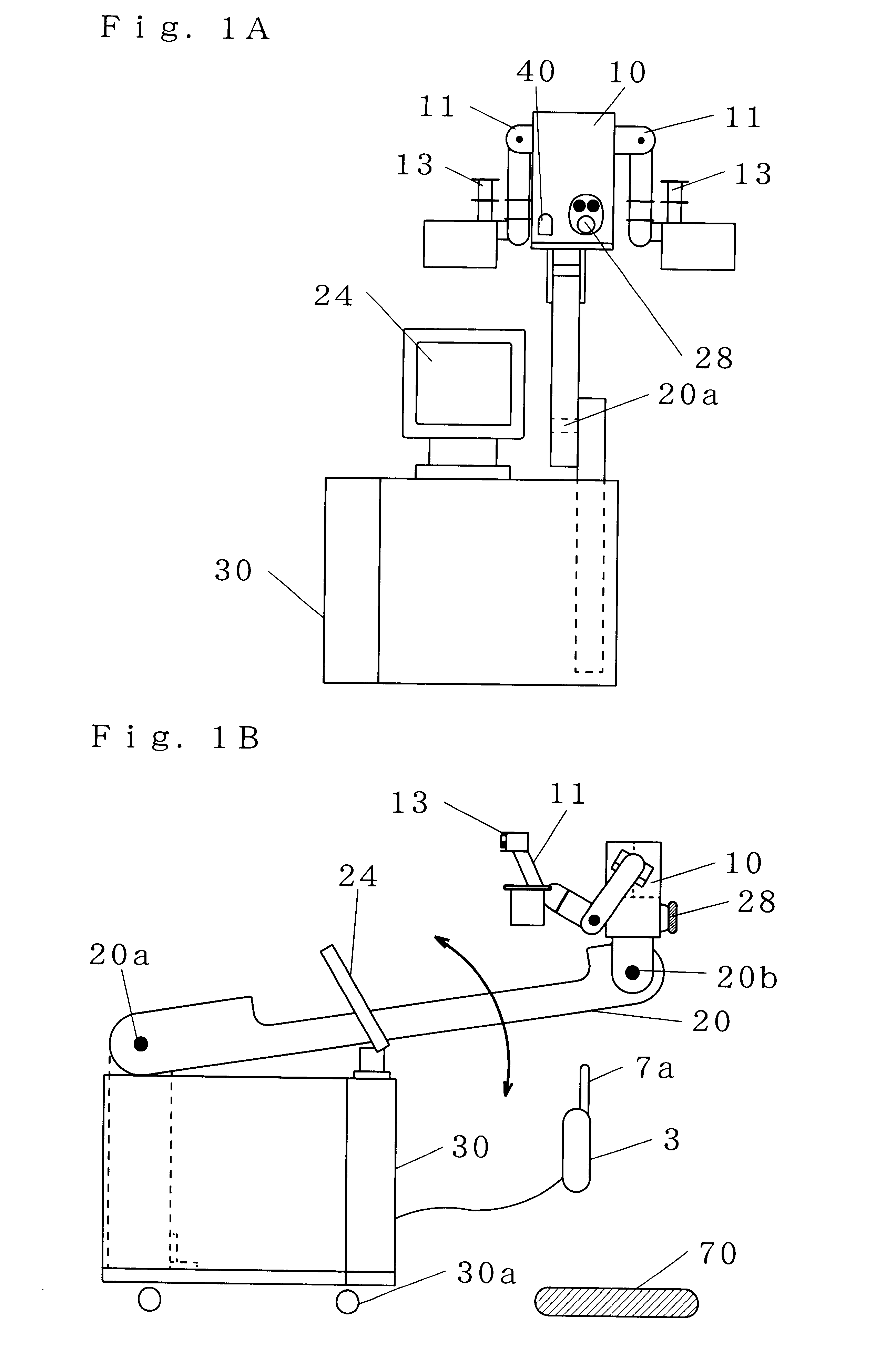
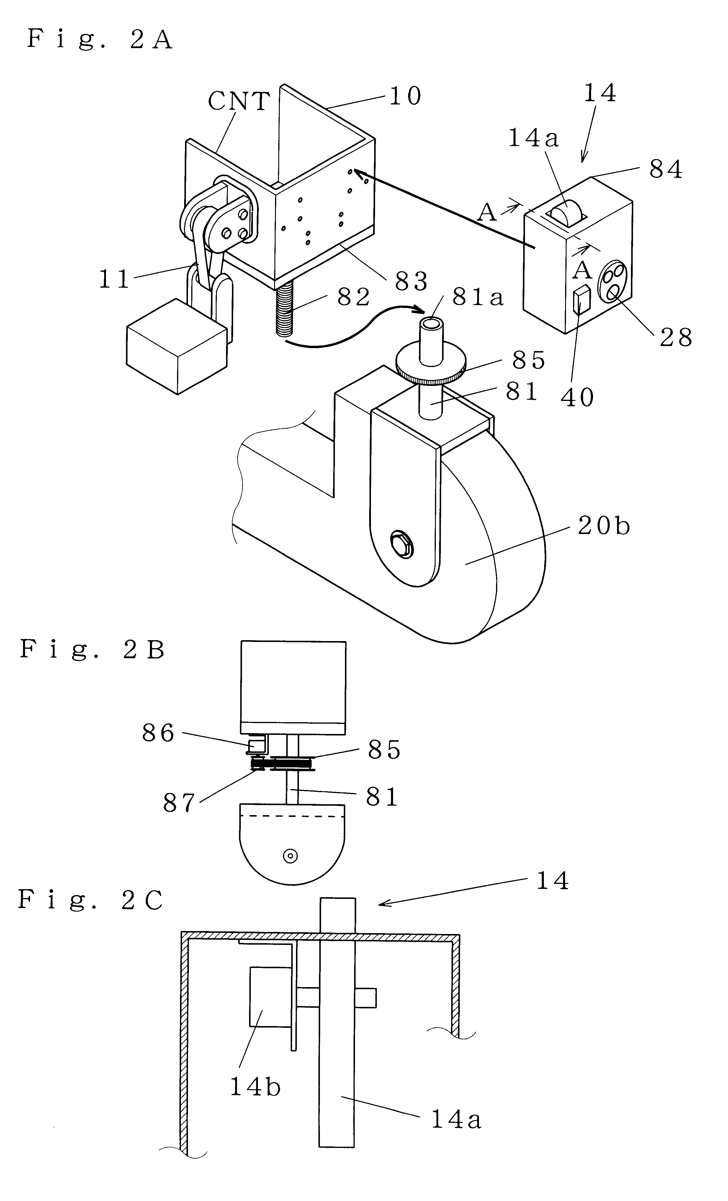
FIG. 1(a) is a front elevational view showing a robot remote controlling apparatus according to the first embodiment of the present invention, and FIG. 1(b) is a left side view showing the robot remote controlling apparatus according to the first embodiment of the invention. In FIG. 1, a mobile communications unit 3 transmits data via a wireless circuit. 7a denotes an antenna. 10 denotes a supporting section. An upper limb portion operating portion 11 carries out finger operations, arm operations and head up and down operations. An up and down moving arm 20 is rotatably disposed on a rack 30 described later, in which the tip end portion 20b thereof moves up and down. 20a denotes the center of rotation of the up and down moving arm. 24 denotes a display for displaying the data. 28 denotes a track ball acting as an input device for inputting data. A rack 30 accommodates a computer apparatus excluding the display 24 and input device 28, and has the display 24 incorporated...


PUM


Abstract

The invention has an object to provide a robot remote controlling apparatus that can easily and comfortably carry out operations at the finger portion operating portion and arm portion operating portion and can easily and comfortably carry out operations at other parts than at the above-described operating portions. The robot remote controlling apparatus includes a rack 30 that accommodates said computer apparatus excluding a display 24 and an input device 28, and at the same time, that mounts the display 24; an up and down moving arm 20 that is rotatably disposed on said rack and whose tip end portion 20b can move up and down; a supporting section 10 rotatably disposed on said tip end portion, which detects a turning angle with respect to said tip end portion as a left and right turning angle of a head portion, and detects a turning angle of a roller 14a disposed on the upper surface thereof as an up and down turning angle of the head portion, and in which said input device 28 is disposed at the front side thereof, and said left and right upper limb portion operating portions 11 are disposed at the left and right sides thereof; and an independent box-shaped leg operating section 70 on which said fuselage operating portion is disposed.

Description

1. Technical Field of the InventionThe present invention relates to a robot apparatus that handles goods by means of respective parts thereof such as the head portion, arm portion and finger portion, etc., and a robot remote controlling apparatus for remotely controlling the robot apparatus via a mobile communications network such as a PHS line, etc.2. Prior ArtsRecently, in line with an increase in work by a robot apparatus, importance has been placed on a robot operating apparatus, which provides instructions such as finger movements and arm movements to the robot apparatus.As a prior art finger portion operating portion that provides movement instructions to the finger portion, there is an input device acting as a data glove that is described in, for example, Japanese Unexamined Patent Publication No. 3465 of 1994. The data glove is such that conductive gel is mounted at the joints of fingers of a glove-shaped input device, and, by utilizing changes in electric resistance values ...

Claims


Application Information

Patent Timeline
Patent Type & Authority Patents(United States)
IPC IPC(8): B25J3/00B25J13/02B25J9/16B25J3/04B25J13/00B25J5/00B25J9/18B25J19/00
CPCB25J3/04B25J9/1689B25J13/02G05B2219/40154G05B2219/33192
Inventor BABA, KATSUYUKIINO, SHIGEAKITAKAMOTO, YOICHI
Owner TMSUK CO LTD
Why Eureka
Try Eureka