Computer heat dissipating structure

a heat dissipating structure and computer technology, applied in the direction of electrical apparatus casings/cabinets/drawers, instruments, semiconductor/solid-state device details, etc., can solve the problems of affecting so as to achieve rapid heat dissipation, reduce the amount of produced heat, and improve the heat dissipation speed

Inactive Publication Date: 2003-11-25
SAINT SONG CORP
View PDF4 Cites 37 Cited by
  • Summary
  • Abstract
  • Description
  • Claims
  • Application Information

AI Technical Summary

Benefits of technology

to provide a computer heat dissipating structure that comprises a lateral blow type fan, which creates a relatively lower air pressure so as to enable a rapid heat dissipation and increase the heat dissipation performance.

Problems solved by technology

This results in an amount of produced heat that is substantially higher.
Because the fan of the above heat dissipating structure produces a downward airflow, a resulting air pressure is relatively high, which impedes a rapid heat dissipation.
Furthermore, the effects of the above heat dissipating structure apply only to one single heat source.
In a computer principal unit, the CPU however operates in cooperation with other chipsets such as the north bridge chipset, which are also heat sources that may undesirably increase the temperature of the principal unit.
To dissipate the heat produced by these other heat sources, other heat dissipating structures, constructed as above, are therefore needed, which increases the production cost and requires a larger mounting space.
Another disadvantage of the above heat dissipating structure of the prior art is that it is relatively higher in size, which may be incompatible with certain computer structures that are dimensionally limited.
As a result, the beneficial effects of fan are limited.
If the fan is continuously operated, it may causes a substantial consumption of power.

Method used


Image

  • Computer heat dissipating structure
  • Computer heat dissipating structure
  • Computer heat dissipating structure

Examples


Embodiment Construction

Wherever possible in the following description, like reference numerals will refer to like elements and parts unless otherwise illustrated.

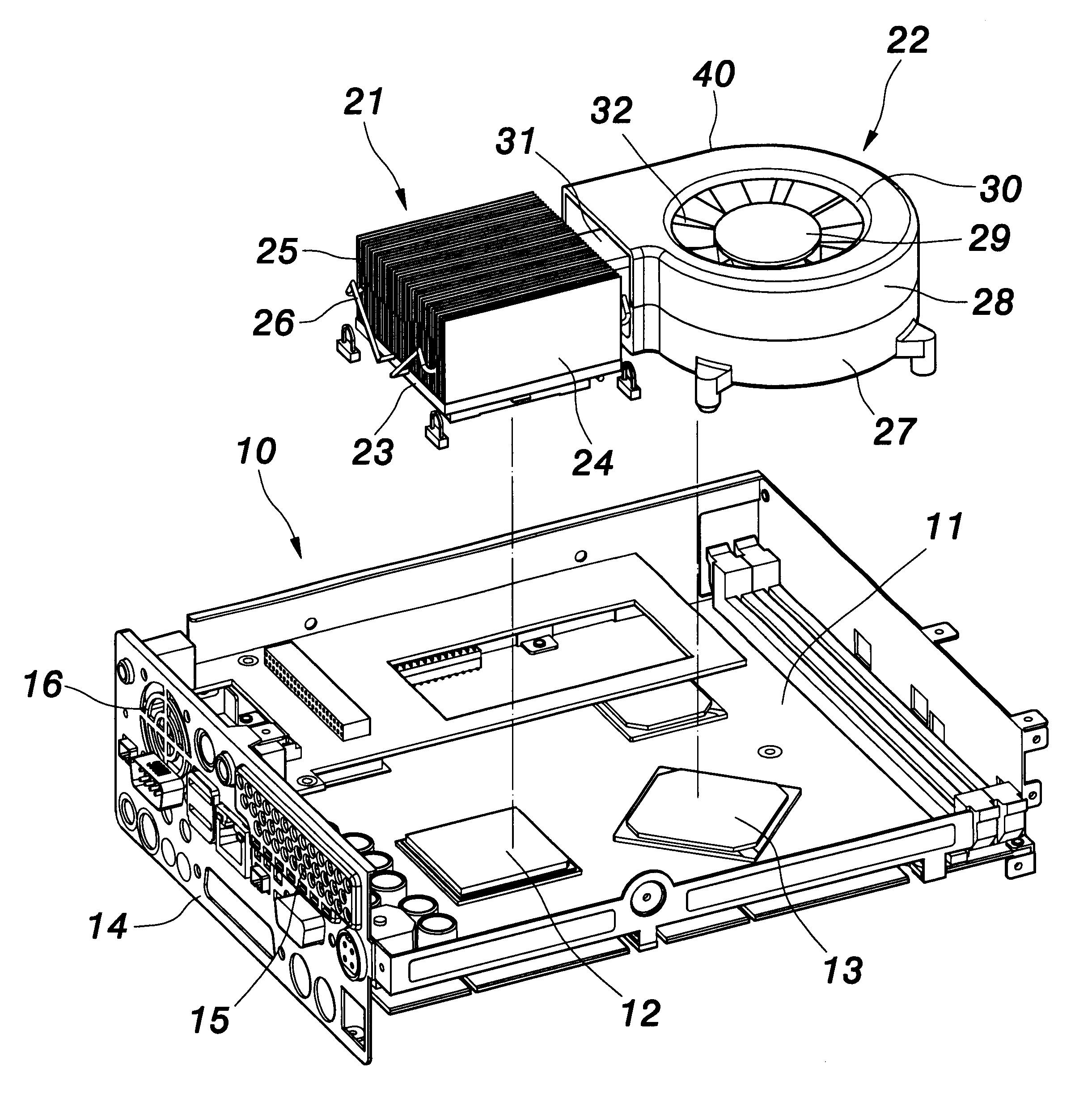
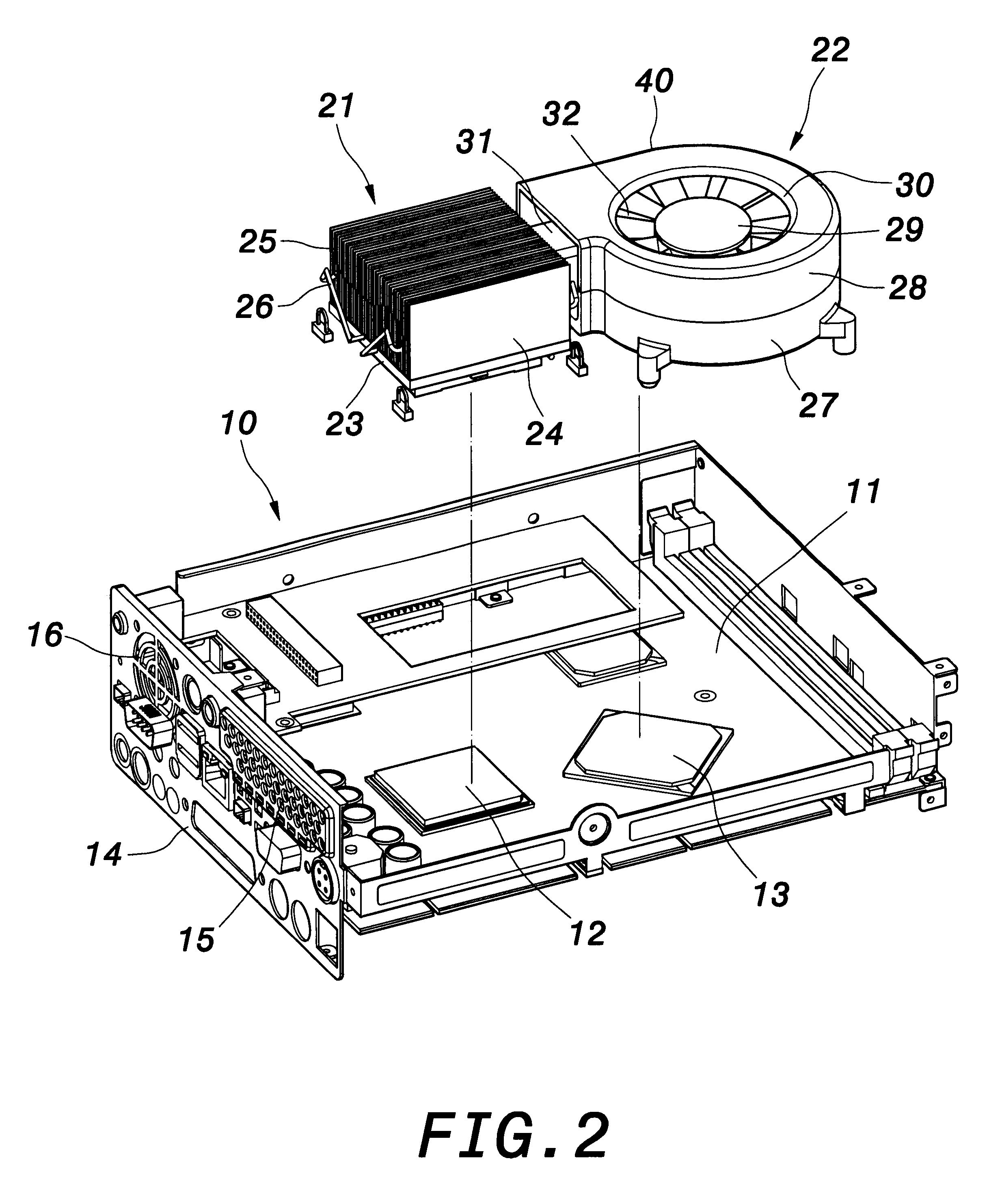
Reference now is made to FIG. 3 through FIG. 4 to describe a computer heat dissipating structure according to an embodiment of the invention. As illustrated, the invention provides a computer heat dissipating structure 20 that is mounted over a computer main board 11, inside a computer principal unit 10, to dissipate the heat irradiated from at least two heat sources 12, 13. The principal heat source 12 is, for example, a central processor unit (CPU). The secondary heat source 13 is, for example, a "north bridge" chipset. The secondary heat source 13 produces an amount of heat that is less than that of the principal heat source 12.

The computer heat dissipating structure 20 comprises a heat sink 21 and a fan 22. The heat sink 21 is made of, for example, aluminum formed by aluminum extrusion, aluminum pouring molding, or aluminum folding. Not limit...


PUM


Abstract

A computer heat dissipating structure of the invention is mounted over a computer main board inside a computer principal unit to dissipate the heat irradiated by at least a principal heat source and a secondary heat source. The computer heat dissipating structure comprises a heat sink that is mounted on the principal heat source, and a fan that is mounted at one lateral side of the heat sink. The fan includes an outer casing that has a lower casing body made of a material having good thermal conduction characteristics. The outer casing further includes an airflow inlet and an airflow outlet that is connected to the heat sink, the lower casing body being placed on the secondary heat source. Via a separate mount of the heat sink and the fan, a lateral blow vis-à-vis the heat sink is thereby achieved to improve the simultaneous heat dissipation of two heat sources.

Description

1. Field of the InventionThe invention relates to a computer heat dissipating structure. More particularly, the invention provides a computer heat dissipating structure. that comprises a lateral blow type fan that is separately mounted in respect of a heat sink to simultaneously dissipate the heat produced by at least two heat sources.2. Description of the Related ArtAs the computer industry advances, the central processor unit (CPU) and the chipsets become increasingly faster. This results in an amount of produced heat that is substantially higher. To maintain the CPU and the chipsets under an acceptable temperature of operation, a heat sink is conventionally mounted to dissipate heat.The heat sink of the prior art is formed principally via aluminum extrusion, pouring molding, or folding. The fabrication of a heat sink by aluminum extrusion or pouring molding is usually constrained by a subsequent mechanical machining process, which therefore limits its thermal dissipation density ...

Claims


Application Information

Patent Timeline
Patent Type & Authority Patents(United States)
IPC IPC(8): G06F1/20H01L23/40H01L23/34H01L23/467H05K7/20
CPCG06F1/20H01L23/4093H01L23/467H01L2924/0002H01L2924/00
Inventor LEE, KUEIR
Owner SAINT SONG CORP
Why Eureka
Try Eureka