Method, system, and device for deploying a containment boom

a containment boom and boom technology, applied in special-purpose vessels, water cleaning, transportation and packaging, etc., can solve the problems of long time-consuming and labor-intensive, long-term environmental hazards of floating oil and/or other fluids on water, and the need for a long containment boom and significant manpower, so as to achieve rapid deployment and short containment boom

Inactive Publication Date: 2003-12-02
JOHNSON RICHARD C
View PDF11 Cites 13 Cited by
  • Summary
  • Abstract
  • Description
  • Claims
  • Application Information

AI Technical Summary

Benefits of technology

The present invention overcomes the above-noted and other shortcomings by providing a novel and improved method, system, and device that meet the aforementioned needs. An embodiment of the present invention is the deployment of an oil spill containment boom that is capable of being attached to the vertical surface of a marine structure (ship, boat, barge, seaplane, submarine, oil rig, pier, etc.) to contain localized areas of spilled oil and/or other fluids that are lighter than water. Because of the features of the present invention and the need for only

Problems solved by technology

Spilled oil and/or other fluids that are lighter than water and, thus, float on water have long been recognized as an environmental hazard.
To cover such a large area requires a lengthy containment boom and significant manpower.
Typically, such a lengthy boom is not carried onboard a ship and is not immediately accessible by dock personnel at pier side.

Method used


Image

  • Method, system, and device for deploying a containment boom
  • Method, system, and device for deploying a containment boom
  • Method, system, and device for deploying a containment boom

Examples


Embodiment Construction

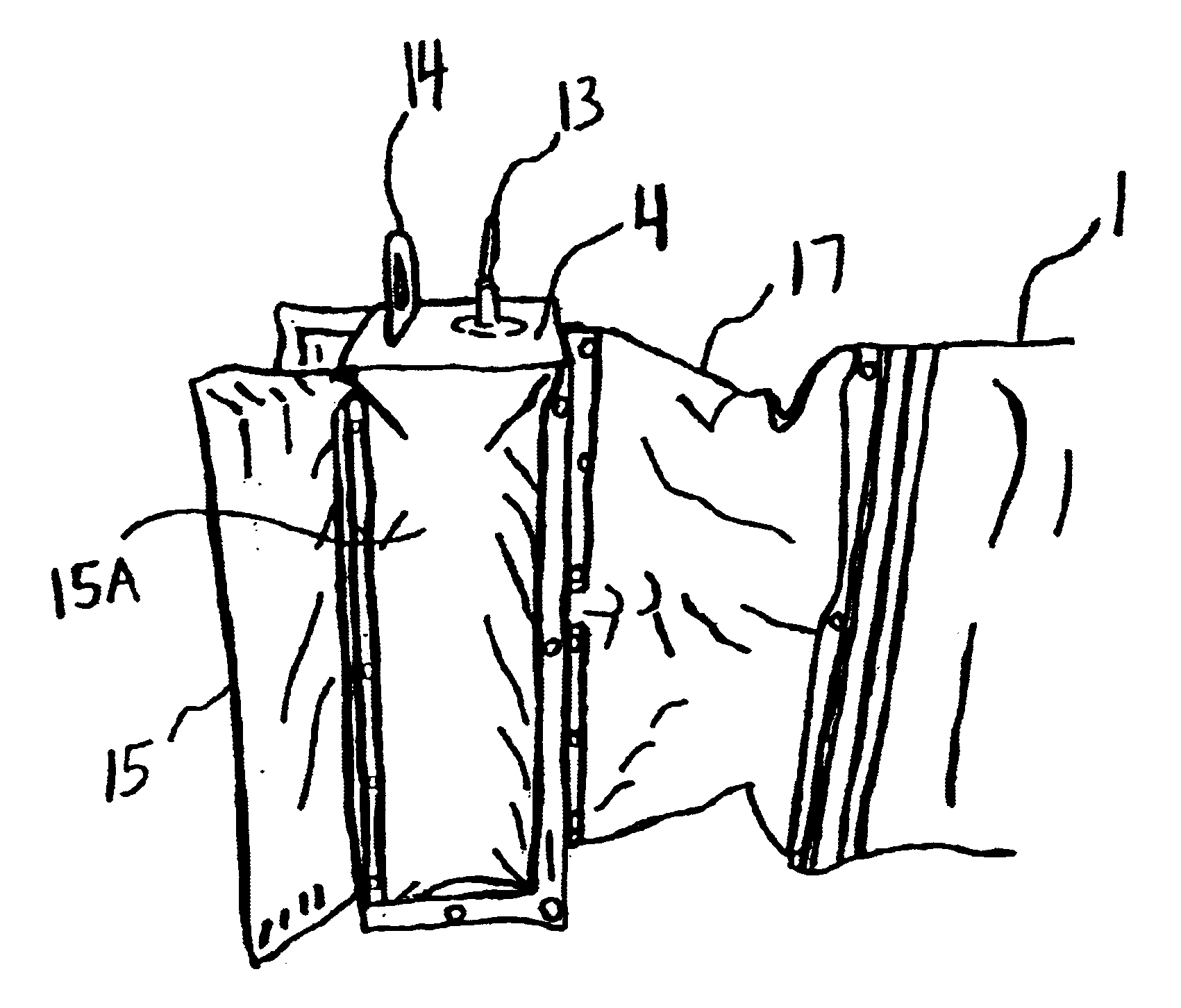
Reference will now be made in detail to embodiments of the invention, one or more examples of which are illustrated in the accompanying drawings. Each example is provided by way of explanation of the invention, not as a limitation of the invention. It will be apparent to those skilled in the art that various modifications and variations can be made in the present invention without departing from the scope or spirit of the invention. For instance, features illustrated or described as part of one embodiment can be used on another embodiment to yield a still further embodiment. Thus, it is intended that the present invention cover such modifications and variations that come within the scope of the appended claims and their equivalents.

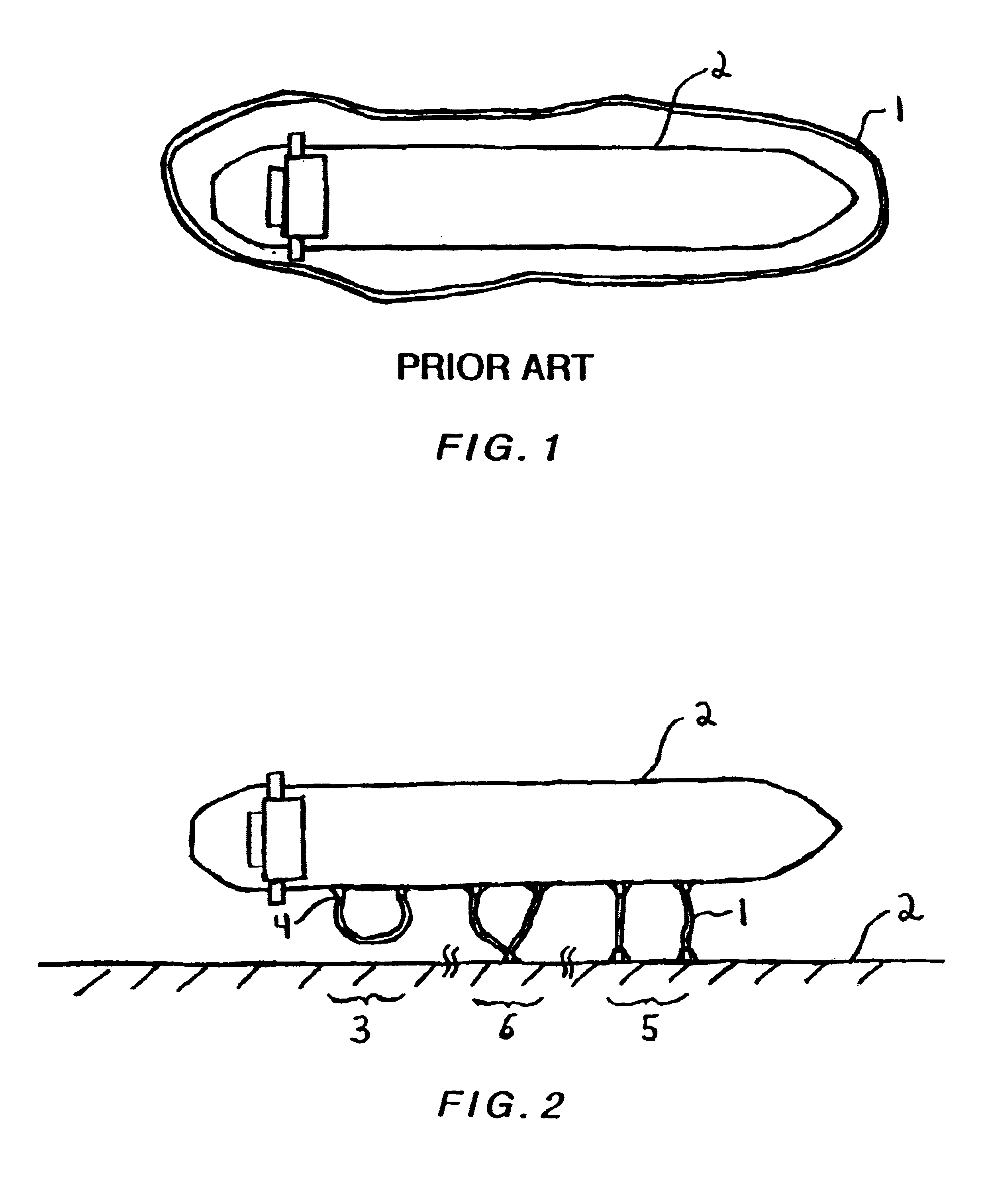
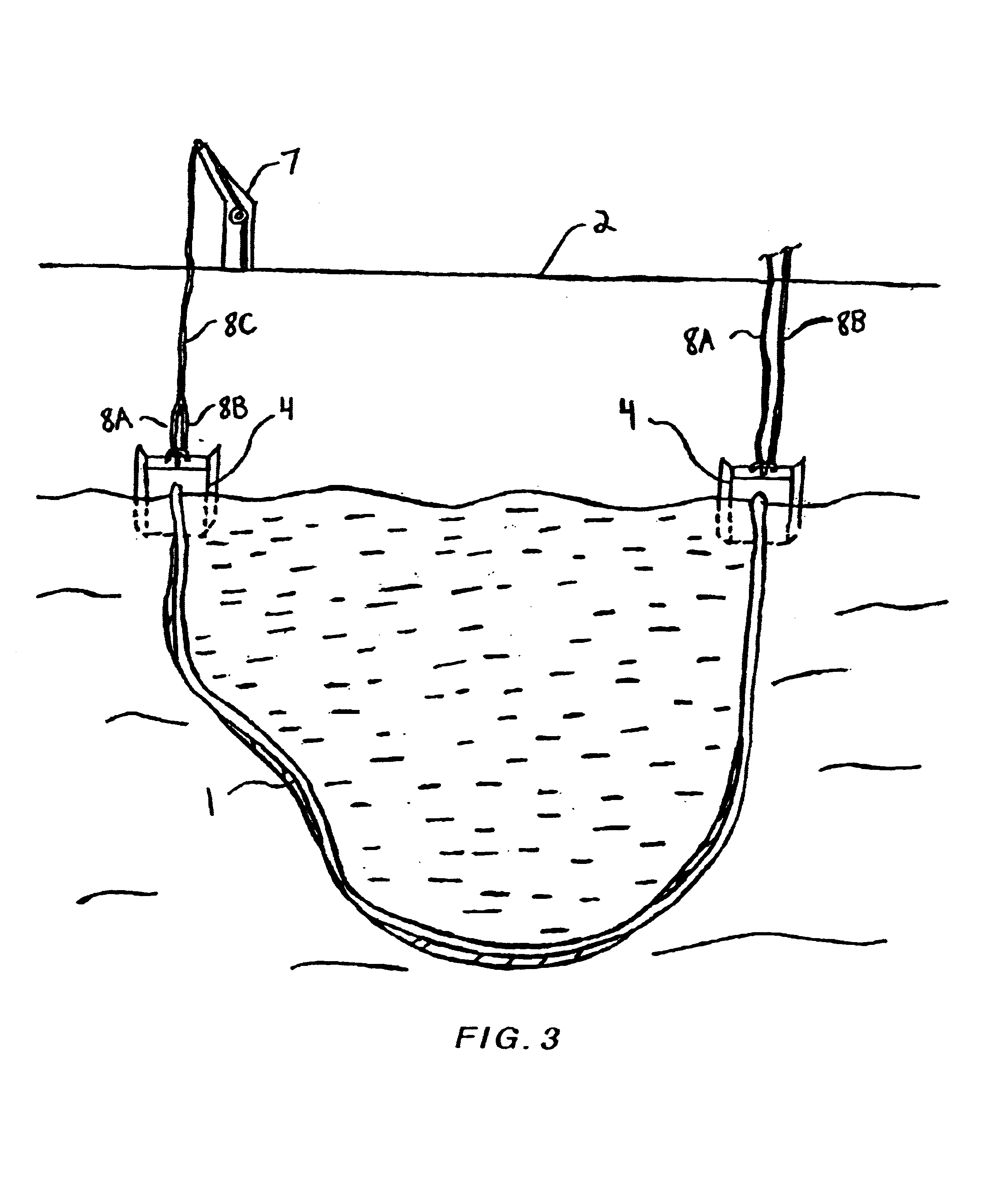
FIG. 1 shows the traditional method for deploying a containment boom 1. The boom 1 fully encircles a marine structure 2, for example, a ship, boat, barge, seaplane, submarine, oil rig, pier, in order to contain fluids that are floating at or near the surf...


PUM


Abstract

A method, system, and device for deploying an oil spill containment boom at the side of a ship, barge, or other steel structure. Each end of the boom is connected to its own device that is configured to attach to a generally vertical surface of a steel-hulled ship. Attachment occurs through the use of magnetic force. Instead of encircling the entire ship with a boom, the device permits the establishment of specific containment areas around the ship. The device engages and disengage the side of the ship through the use of a cam and lever assembly to counter the magnetic force.

Description

FIELD OF THE INVENTIONThe present invention relates generally to a method, system, and device for attaching an object near the waterline of a marine structure. More particularly, but not by way of limitation, the invention relates to a method, system, and device for deploying an oil spill containment boom by magnetically attaching the ends of the boom to the side of a ship's hull.BACKGROUNDSpilled oil and / or other fluids that are lighter than water and, thus, float on water have long been recognized as an environmental hazard. At the same time, the transportation of oil and other fluids by ships, barges and other vessels on waterways is becoming more prevalent.When an oil spill occurs, the common method for containing the spill is to surround the entire marine structure (ship, boat, barge, seaplane, submarine, oil rigs, pier, etc.) that is the source of the spill, as well as, the spilled oil. To cover such a large area requires a lengthy containment boom and significant manpower. To...

Claims


Application Information

Patent Timeline
IPC IPC(8): B63B35/32E02B15/04
CPCB63B35/32E02B15/08E02B15/085E02B15/0835E02B15/0828Y02A20/204
Inventor JOHNSON, RICHARD C.
Owner JOHNSON RICHARD C
Why Eureka
Try Eureka