

Method and apparatus for measuring gap, method and apparatus for measuring shape and method for manufacturing liquid crystal device
a technology of liquid crystal devices and measuring devices, applied in the direction of optical radiation measurement, instruments, spectrometry/spectrophotometry/monochromators, etc., can solve the problems of time-consuming and labor-intensive problems, and achieve the effect of reducing labor intensity and reducing labor intensity
- Summary
- Abstract
- Description
- Claims
- Application Information
AI Technical Summary
Problems solved by technology
Method used
Image

Examples
third embodiment
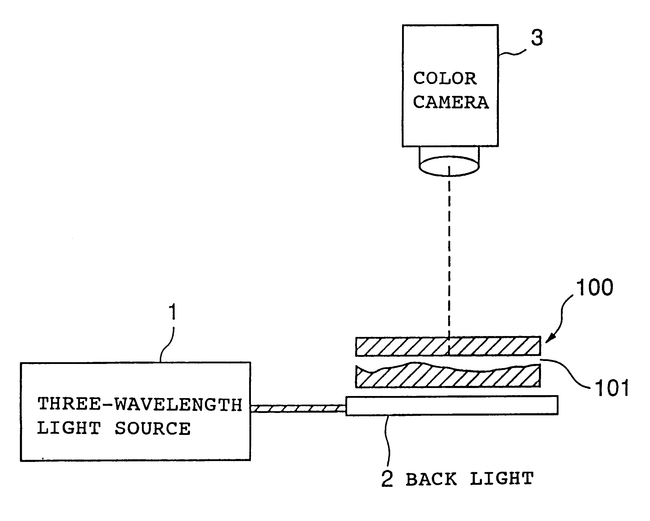
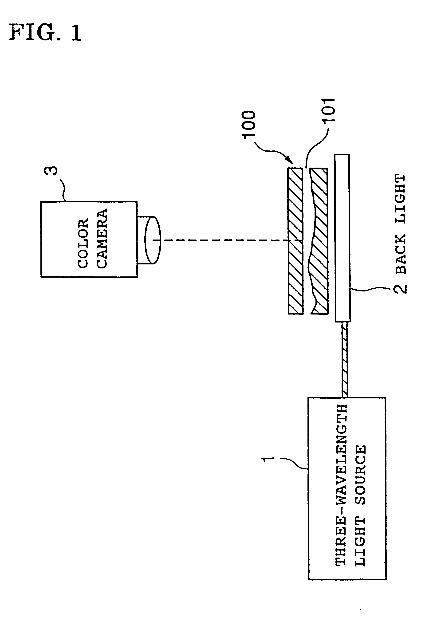
FIG. 13 is configuration diagram showing a seventh optical system for obtaining a color image of an interference fringe according to one embodiment of the present invention. Lights from a three-wavelength light source 1 that emits color lights with a plurality of different wavelengths (hereinafter, referred to as three types of color lights such a blue light, green light, and red light) are reflected toward an object to be measured 200 and a transparent plate shaped element 7 having a gap relate to the object to be measured 200 and having a flat surface disposed oppositely. The resultant lights are reflected by the object to be measured 200 and transparent plate shaped element 7. Further, the reflected light is forced to transmit a beam splitter 6, and the transmitted light is shot by the color camera 3, thereby shooting an interference fringe caused by a gap 201 formed by the object to be measured 200 and transparent plate shaped element 7.
fourth embodiment
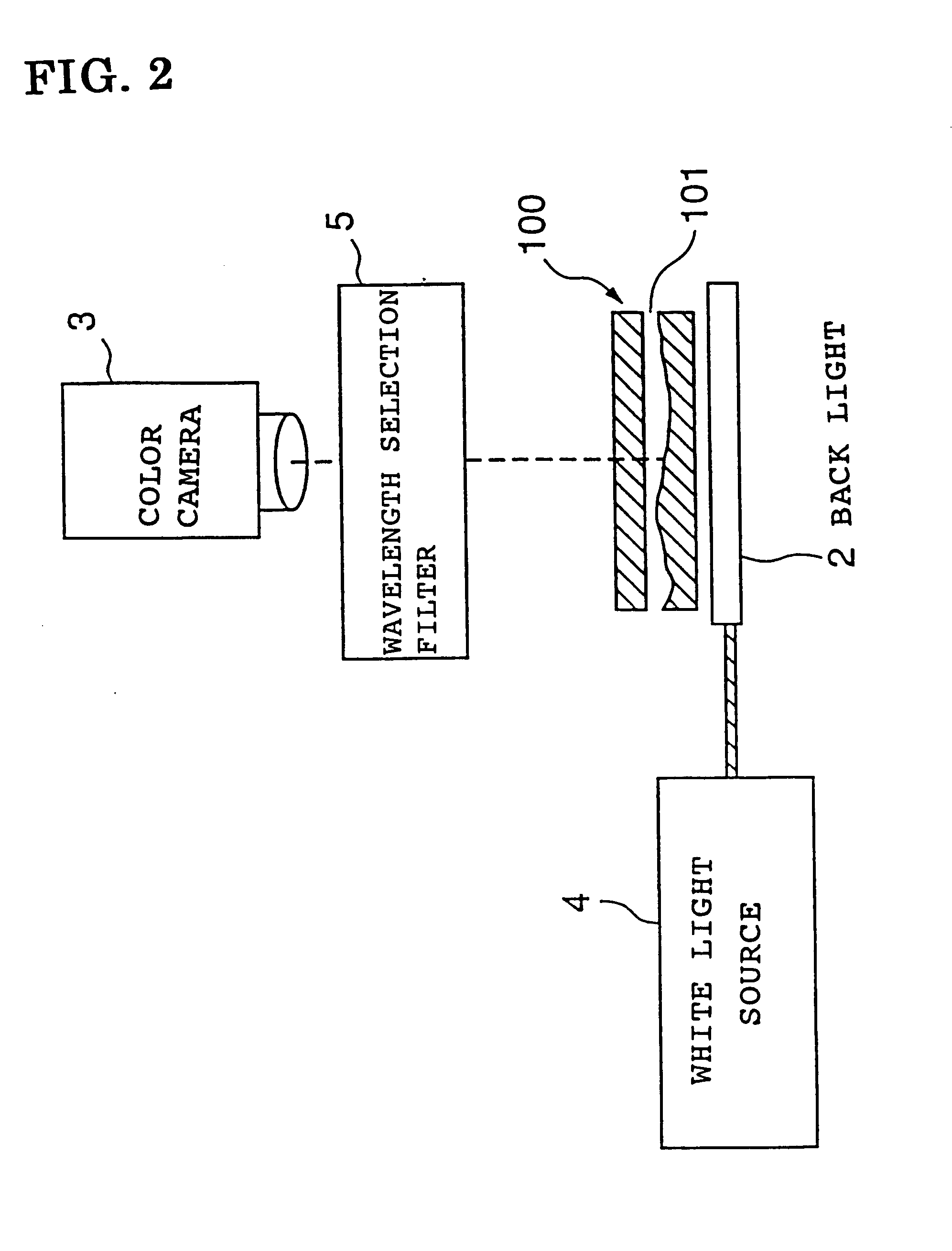
FIG. 14 is a configuration diagram showing an eighth optical system for obtaining a color image of an interference fringe according to one embodiment of the present invention. The light from a white light source 4 is reflected toward an object to be measured 200 and a transparent plate shaped element 7 having a gap relate to a measurement face of the object to be measured 200 and having a flat surface disposed oppositely. The resultant light is reflected by the object to be measured 200 and transparent plate shaped element 7. Further, the reflected light is forced to transmit a beam splitter 6, and the transmitted light is shot by a color camera 3, thereby shooting an interference fringe caused by a gap 201 formed by the object to be measured 200 and transparent plate shaped element 7. At this time, the color camera 3 comprises a wavelength selection filter 5 that selectively transmits color lights with a plurality of different wavelengths thereinafter, referred to as three types of...
fifth embodiment
FIG. 15 is configuration diagram showing a ninth embodiment for obtaining a color image of an interference fringe according to one embodiment of the present embodiment by using a principle of a so called Michaelson's interferometer. Lights from a three-dimensional wavelength light source 1 that emits color lights with a plurality of different wavelengths (hereinafter, referred to as three types of color lights such as blue light, green light, and red light) are reflected toward an object to be measured 200 via a beam splitter 8, the resultant lights are reflected by the object to be measured 200, and further, the reflected lights are forced to transmit the beam splitter 8. At the same time, the lights from the three-wavelength light source 1 are transmitted toward a reference mirror 9 by the beam splitter 8, and the lights are reflected by the object to be measured 200, and the reflected lights are reflected by the beam splitter 8. Such reflected light from the object to be measured...
PUM
| Property | Measurement | Unit |
|---|---|---|
| wavelengths | aaaaa | aaaaa |
| wavelengths | aaaaa | aaaaa |
| color camera | aaaaa | aaaaa |
Abstract
Description
Claims
Application Information