Lockbolt for forming a mechanically secured and sealant sealed connection between components

a technology of mechanical sealing and locking collars, which is applied in the direction of bolts, threaded fasteners, screws, etc., can solve the problems of contaminating the sealant still reaches and contaminates the annular circumferential groove, and the proper function of mechanical sealing connections cannot be reliably and completely guaranteed

Inactive Publication Date: 2003-12-09
AIRBUS OPERATIONS GMBH
View PDF11 Cites 29 Cited by
  • Summary
  • Abstract
  • Description
  • Claims
  • Application Information

AI Technical Summary

Benefits of technology

The knurling of the locking portion of the bolt shaft provides the necessary mechanical gripping and locking structures onto which the locking collar is deformed, i.e. crimped or swaged, in order to establish a secure mechanical connection of the locking collar onto the locking portion of the bolt shaft, and thereby to securely mechanically join the workpieces between the bolt head and the locking collar, with the bolt shaft extending through aligning holes provided in the workpieces.
Moreover, the knurling allows the sealant between the locking collar and the knurled surface of the locking portion of the bolt shaft to be distributed, and any excessive sealant to be squeezed-out, as follows. When the shaft of the locking bolt is inserted through the aligned holes of the workpieces, which have been sealed with a sealant, the sealant becomes smeared or wiped onto the shaft of the bolt, including the locking portion thereof. When the locking collar is deformed and locked onto the knurled surface of the locking portion of the bolt shaft, the knurling grooves allow the sealant to become uniformly spread out to form a thin surfacial sealant layer or film over the knurled surface, i.e. between the knurling and the inner surface of the locking collar being deformed onto the knurling. Thereby, this thin sealant layer provides an additional sealing and adhesive function without hindering the mechanical swaging or deforming interconnection of the locking collar onto the knurled surface of the locking portion of the bolt shaft.
A significant advantage of the invention is that the knurling provided on the surface of the locking portion of the bolt shaft effectively prevents the formation of encapsulated chambers, and instead provides venting and sealant-escape-paths between the locking portion and the locking collar, as the locking collar is deformed or swaged onto the locking portion of the bolt shaft. Particularly, the knurling grooves provide an outlet for the excess sealant to escape or be squeezed-out from between the locking collar and the locking portion of the bolt shaft along these knurling grooves, and also achieves a targeted distribution of a small remaining amount of sealant to form a thin sealant layer or film between the locking collar and the locking portion of the bolt shaft, as follows. During the joining or securing process, the locking collar is securely deformed in a force-locking manner onto the knurling peaks, but the locking collar preferably and advantageously does not completely penetrate into and fill the bottom of the knurling grooves or the shaft base surface between the knurling peaks. This leaves gap channels at the bottom of the knurling grooves, i.e. free gap channels between the knurling base surface and the locking collar, in which the sealant can uniformly distribute itself. In this manner, the formation of an enclosed or encapsulated, pressurized hydraulic buffer (which would be the case in a continuous circumferential extending annular groove) is avoided during the swaging deformation of the locking collar, because the knurling includes spiral grooves that extend helically in the axial direction so as to interrupt and open-up any isolated grooves such as circumferentially extending grooves.
Instead of a knurling pattern including spiral knurling grooves, it is alternatively possible to provide a knurling pattern formed by the intersection of circumferentially extending grooves and axially extending grooves. With such a knurling pattern, the axially extending grooves provide the venting or sealant-distributing function to prevent the formation of a sealed, encapsulated hydraulic buffer of sealant material enclosed in a continuous circumferentially extending groove. A generalized feature of an embodiment of the invention is thus that the knurling pattern includes grooves that extend in a direction having an axial component, so as to prevent the formation of enclosed cells or hydraulic buffers in which the sealant becomes trapped between the bolt shaft surface and the locking collar.

Problems solved by technology

In actual practice, while the O-ring wipes some sealant out of the bored hole of the workpieces and thus ahead of and away from the locking grooves of the bolt, some sealant nevertheless still reaches and contaminates the annular circumferential grooves.
Thus the proper functionality of the mechanical swaged connection cannot be reliably and completely ensured in the event of a remaining contamination of the parts of the bolts.
This is especially problematic due to the annular circumferential configuration of the locking grooves of the locking portion of the known bolts.
As a result, the locking collar cannot be properly and completely swaged onto the locking portion of the bolt shank, so that an adequate mechanical holding power cannot be achieved.
Moreover, a further disadvantage is that the O-rings must be individually installed on the individual lockbolts, and after the bolt-securing process, the O-rings must be tediously removed, if they have not fallen away by themselves.

Method used


Image

  • Lockbolt for forming a mechanically secured and sealant sealed connection between components
  • Lockbolt for forming a mechanically secured and sealant sealed connection between components
  • Lockbolt for forming a mechanically secured and sealant sealed connection between components

Examples


Embodiment Construction

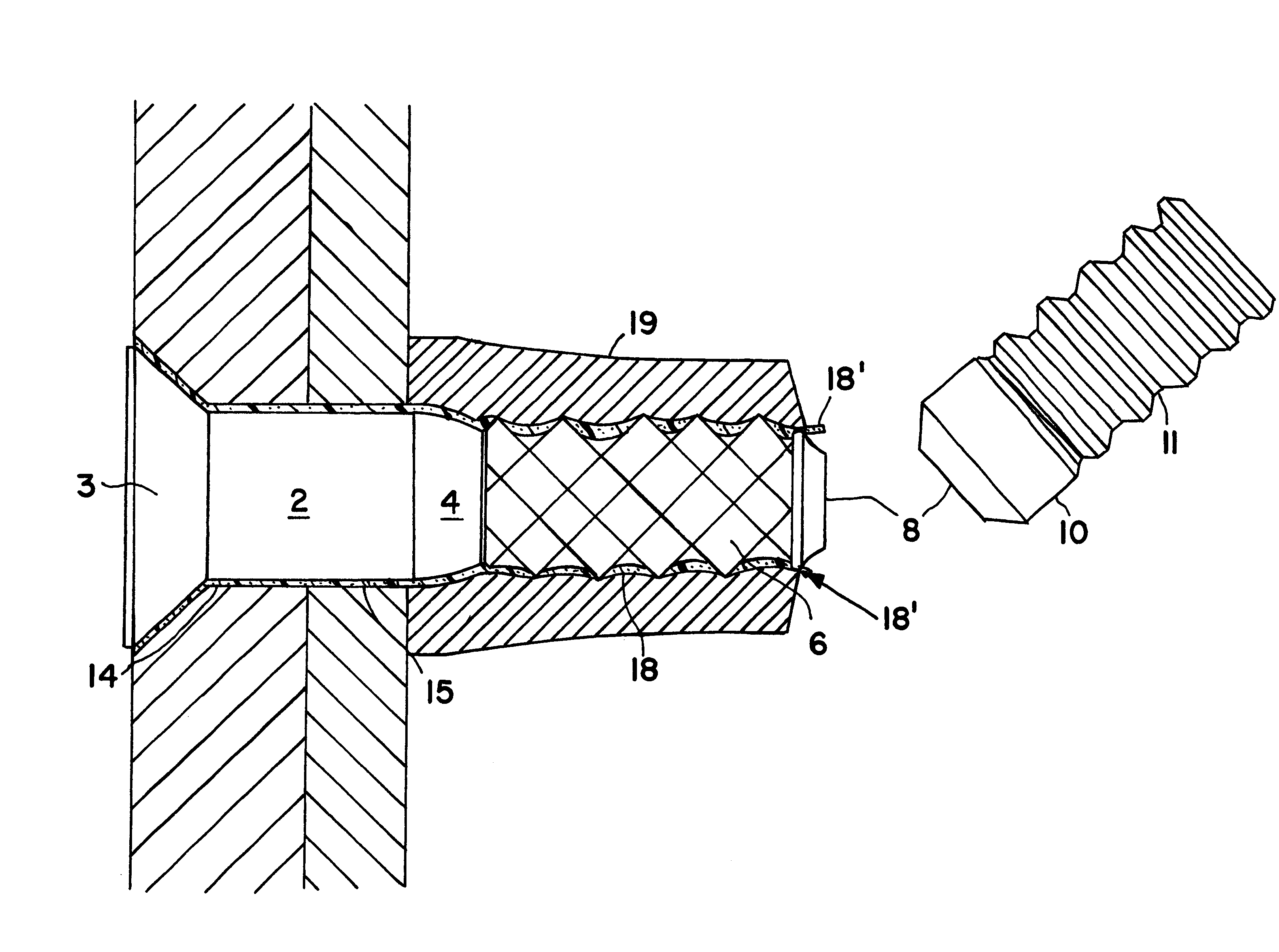
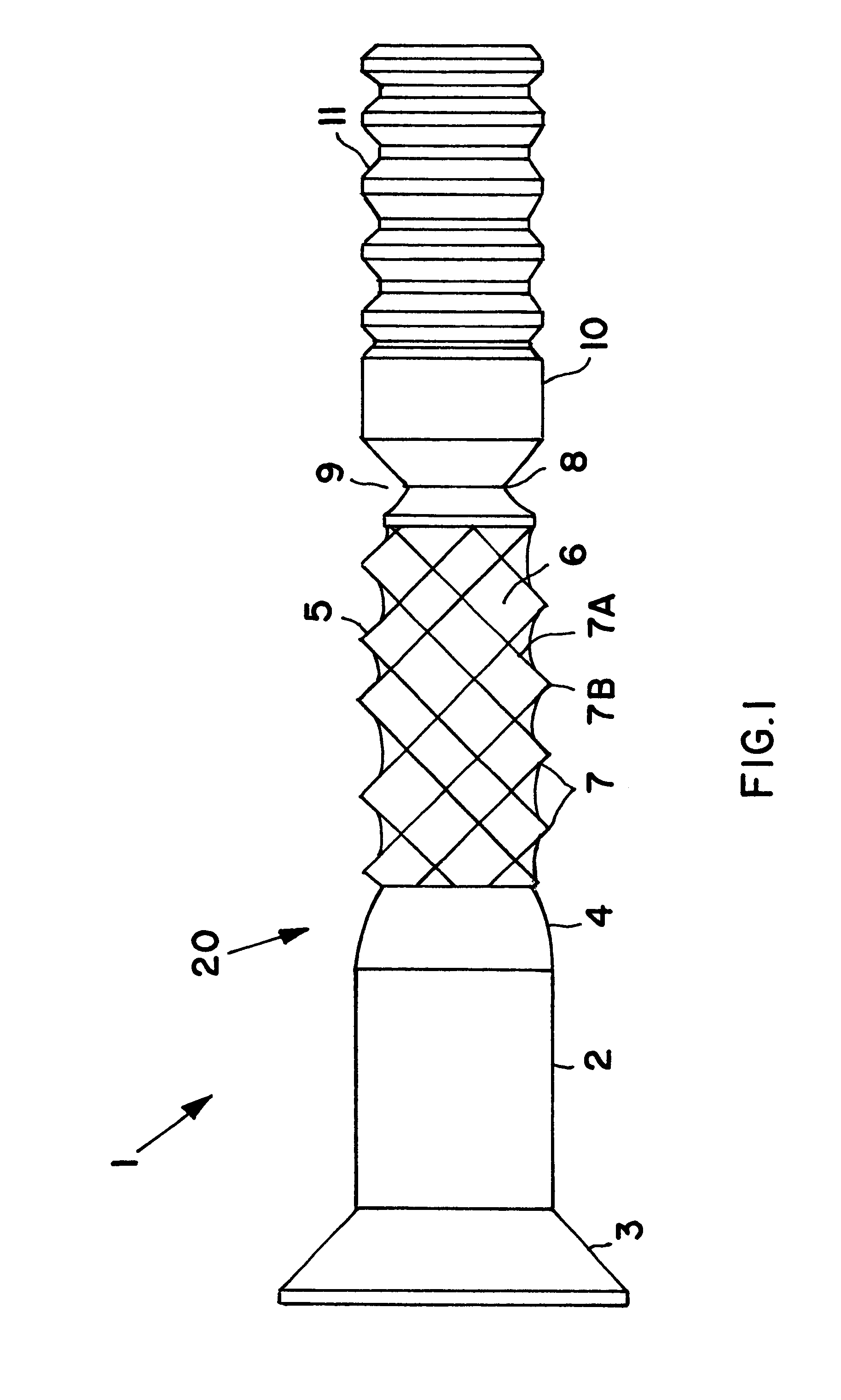
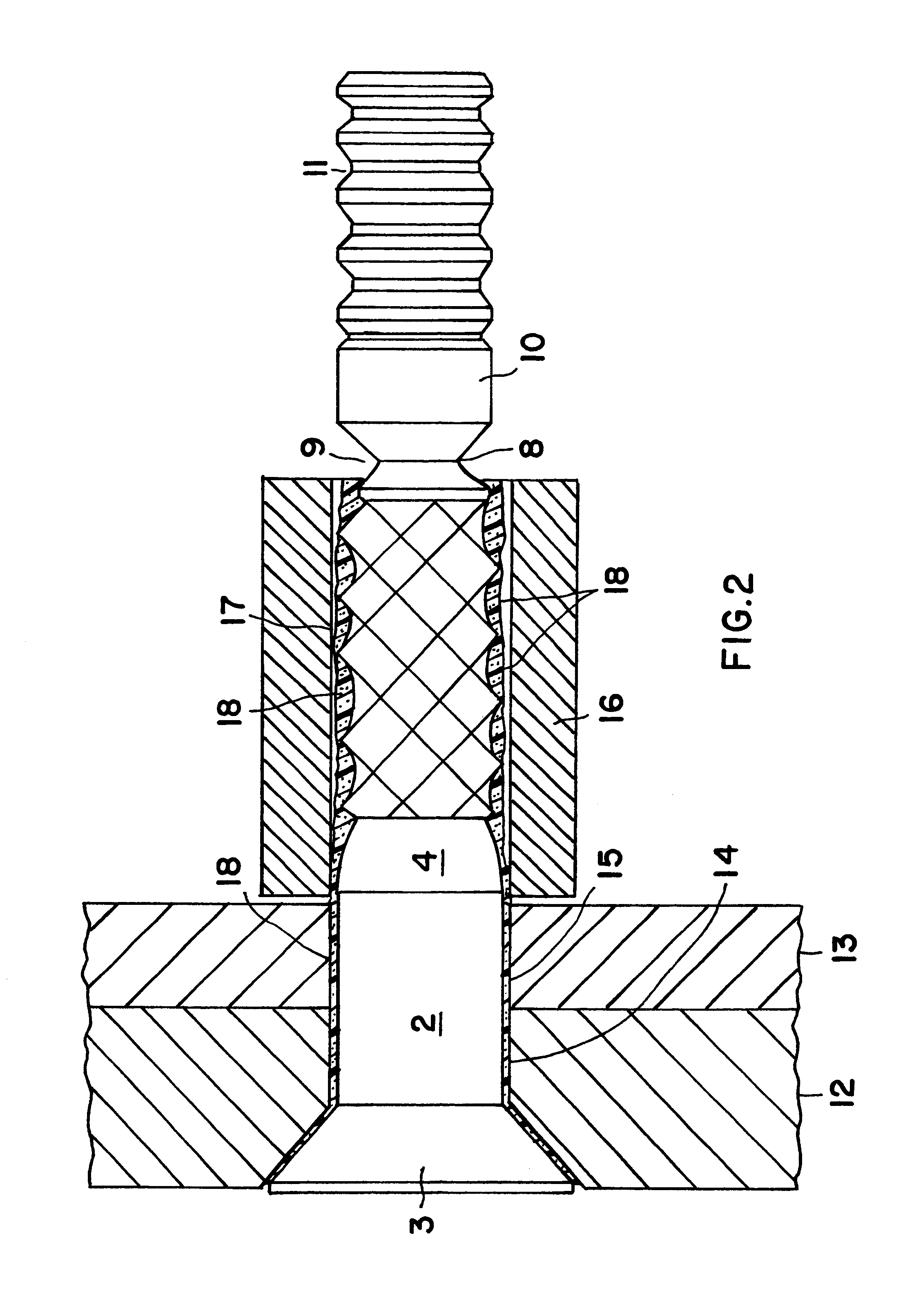
As shown in FIG. 1, a lockbolt 1 includes a flat countersunk head 3 mechanically rigidly connected to one end of a generally cylindrical shaft 20. Instead of the countersunk head 3, the lockbolt may have any other conventionally known head configuration, such as a cylindrical head, a pan head, a round head, or the like. Adjoining the bolt head 3, the shaft 20 includes a cylindrical shank 2, which transitions through a preferably conically tapering portion 4 into a profiled or surface-patterned locking portion 5. The surface profiling of this locking portion 5 comprises a knurling 6 therearound, made up of knurling peaks 7B bounded by knurling flanks 7, between respective adjacent knurling grooves 7A. In this embodiment, the knurling peaks 7B are essentially diamond-shaped, i.e. having a pyramid shape with a four-sided diamond-shaped base, and the knurling grooves 7A include two sets of grooves respectively extending in opposite spiral directions helically around the surface of the b...


PUM

PropertyMeasurementUnit
mechanical engagementaaaaaaaaaa
shapeaaaaaaaaaa
pyramid shapeaaaaaaaaaa

Abstract

A lockbolt includes a bolt head, a shank, a locking portion, a predetermined breaking point, and a break-away portion. The locking portion includes a knurled surface having knurling peaks between intersecting knurling grooves that extend in a direction with an axial component, e.g. spiraling helically. A sealant on two workpieces smears onto the knurled surface when the bolt is inserted in a hole therein, but does not need to be removed. A locking collar is swaged onto the locking portion to secure the workpieces between the head and the collar. The sealant is distributed as a thin layer to provide a seal and an adhesive bond between the collar and the knurled surface. Excess sealant is squeezed-out axially, without forming encapsulated pressurized sealant pockets and without hindering the swaged engagement of the locking collar onto the knurling. Then the break-away portion is broken-off at the breaking point.

Description

PRIORITY CLAIMThis application is based on and claims the priority under 35 U.S.C. .sctn.119 of German Patent Application 101 07 952.4, filed on Feb. 20, 2001, the entire disclosure of which is incorporated herein by reference.1. Field of the InventionThe invention relates to a lockbolt with a locking collar such as a swageable collar for mechanically securing two or more components, i.e. workpieces, through a hole that has been sealed with a sealant.2. Background InformationIt is generally known to use lockbolts for forming high-strength mechanical joints of two or more workpieces, for example in the field of aircraft manufacturing. The lockbolt is secured in aligned holes through the workpieces, which have been sealed or provided with a sealant. The lockbolt includes a shaft that extends through the holes in the workpieces, and a bolt head at one end of the shaft, whereby the head lies against the outer surface of one of the workpieces. The other end of the shaft that protrudes ou...

Claims


Application Information

Patent Timeline
Patent Type & Authority Patents(United States)
IPC IPC(8): F16B19/04F16B19/05
CPCF16B19/05Y10T29/49929
Inventor STOEWER, UDO-HENNINGTURLACH, GERHARD
Owner AIRBUS OPERATIONS GMBH
Why Eureka
Try Eureka