
DMOS transistor protected against polarity reversal

a technology of polarity reversal and dmos transistor, which is applied in the direction of semiconductor devices, semiconductor/solid-state device details, electrical apparatus, etc., can solve the problems of voltage drop that is undesirable per se, destruction of dmos transistor or to a voltage supply arranged in fron

Inactive Publication Date: 2003-12-09
ROBERT BOSCH GMBH
View PDF10 Cites 0 Cited by
  • Summary
  • Abstract
  • Description
  • Claims
  • Application Information

AI Technical Summary

Problems solved by technology

Especially in the case of large short-circuit currents, this can lead to the destruction of the DMOS transistor or to a voltage supply arranged in front of it.
Besides the high area requirement, it is disadvantageous in this circuit configuration that the high resistance to blocking of the switching transistor leads to a correspondingly high forward resistance in the conducting case, which leads to a voltage drop that is undesirable per se.

Method used


Image

  • DMOS transistor protected against polarity reversal
  • DMOS transistor protected against polarity reversal
  • DMOS transistor protected against polarity reversal

Examples


Embodiment Construction

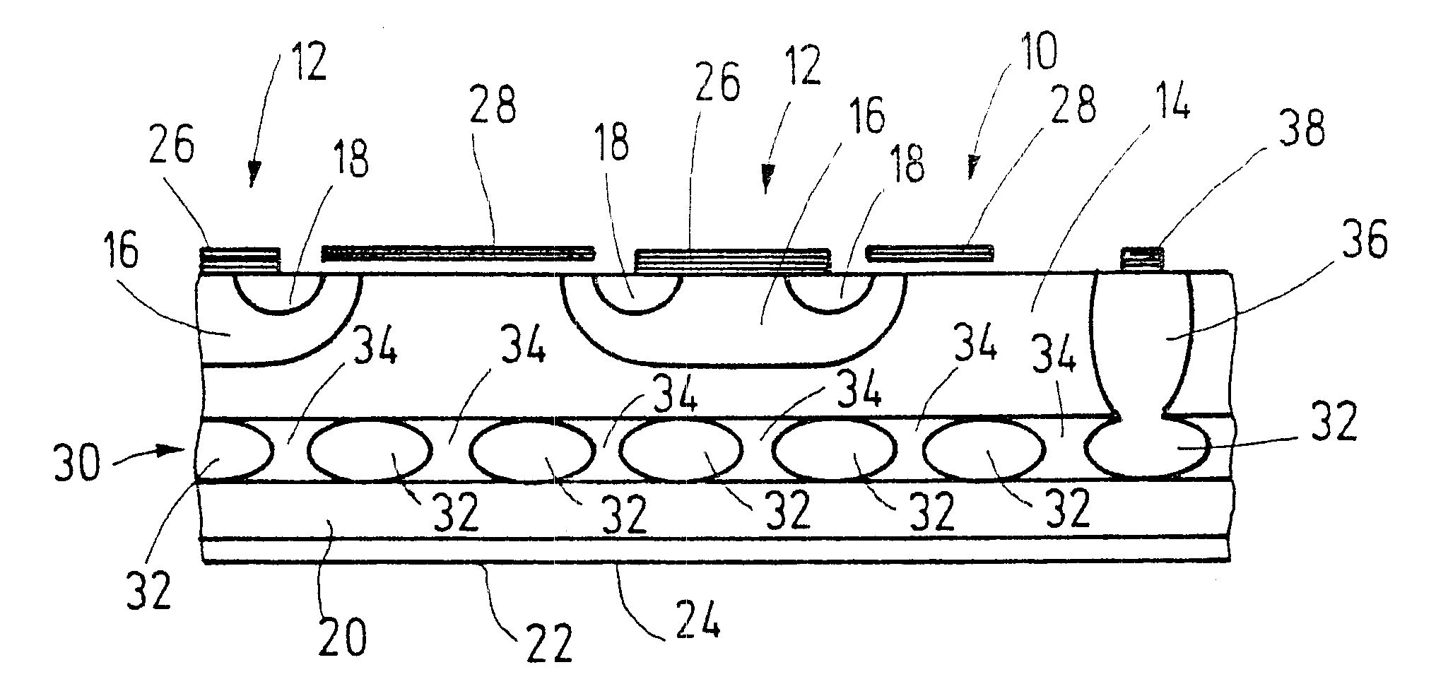
FIG. 1 shows a DMOS transistor 10. The DMOS transistor is shown in a section in the region of two control heads 12.

The DMOS transistor includes a drift zone 14 having a charge carrier doping (let us say n-doped). Charge carrier zones 16, having a charge carrier doping (p-doped in the example) opposite to the first charge carrier doping, are integrated into drift zone 14. Into charge carrier zones 16, additional charge carrier zones 18 are integrated which have the same charge carrier doping as drift zone 14 (n.sup.+ -doped in the example). Drift zone 14 is situated on a substrate region 20, which is equivalent to the same charge carrier type as drift zone 14, but has a higher doping (n.sup.+ -doped in the example). Substrate region 20 is furnished with a metallization 22. The metallization forms a drain terminal 24 of DMOS transistor 10. Charge carrier zones 16 and 18 are connected in an electrically conducting manner via metallizations 26. Metallizations 26 form surce connections o...


PUM


Abstract

The present invention relates to a circuit configuration for protecting against polarity reversal of a DMOS transistor.A charge carrier zone (30) is provided, situated in the drift zone (14) of DMOS transistor (10), made up of individual partial charge carrier zones (32) situated at a distance from one another and connected to one another in a conducting manner, the charge carrier zone (30) having an opposite charge carrier doping from that of the drift zone (14), and being able to be acted upon by a potential that is negative with respect to a potential present at a drain terminal (24) of the DMOS transistor (10), so that a short-circuit current is prevented.

Description

The present invention relates to a circuit configuration for protecting against polarity reversal of a DMOS transistor.BACKGROUND INFORMATIONWhen DMOS transistors are inserted into circuit configurations in which there are at least two supply voltages available, in case of a fault, for instance a short-circuit, it may happen that a short-circuit current runs backwards via the DMOS transistor. Especially in the case of large short-circuit currents, this can lead to the destruction of the DMOS transistor or to a voltage supply arranged in front of it.A circuit configuration is known from DE 195 02 731 C2 in which a polarity-reversal protecting DMOS transistor is allocated to a DMOS transistor that is in series with a load circuit to be switched. In this case, the transistors are connected antiserially and monolithically integrated in a common substrate. Because both the switching transistor and the polarity reversal protection transistor are integrated in a common substrate having a c...

Claims


Application Information

Patent Timeline
IPC IPC(8): H01L29/78H01L29/66H01L29/08H01L29/02H01L21/336H01L27/04
CPCH01L29/7832H01L29/7802H01L29/7803H01L29/0623H01L29/0847H01L29/0878
Inventor PLIKAT, ROBERTFEILER, WOLFGANG
Owner ROBERT BOSCH GMBH
Features
  • Generate Ideas
  • Intellectual Property
  • Life Sciences
  • Materials
  • Tech Scout
  • Unparalleled Data Quality
  • Higher Quality Content
  • 60% Fewer Hallucinations
Learn More