
Coding device, coding method, decoding device, decoding method, program recording medium and data recording medium

a coding device and coding method technology, applied in the field of coding devices, coding methods, decoding devices, and decoding methods, can solve the problems of unsatisfactory characteristic value, unsatisfactory actual noise sense, and inability to achieve satisfactory characteristic value, etc., to achieve the effect of high-speed operation and non-optimal effect of actual nois

Inactive Publication Date: 2003-12-09
SONY CORP
View PDF23 Cites 13 Cited by
  • Summary
  • Abstract
  • Description
  • Claims
  • Application Information

AI Technical Summary

Benefits of technology

In view of the foregoing status of the art, it is an object of the present invention to provide a coding device and method which enables generation of a code string having a compression rate changed at a high-speed with a small quantity of operation.
It is a further object of the present invention to provide a data recording medium in which a code string having a compression rate changed at a high speed with a small quantity of operation is recorded.
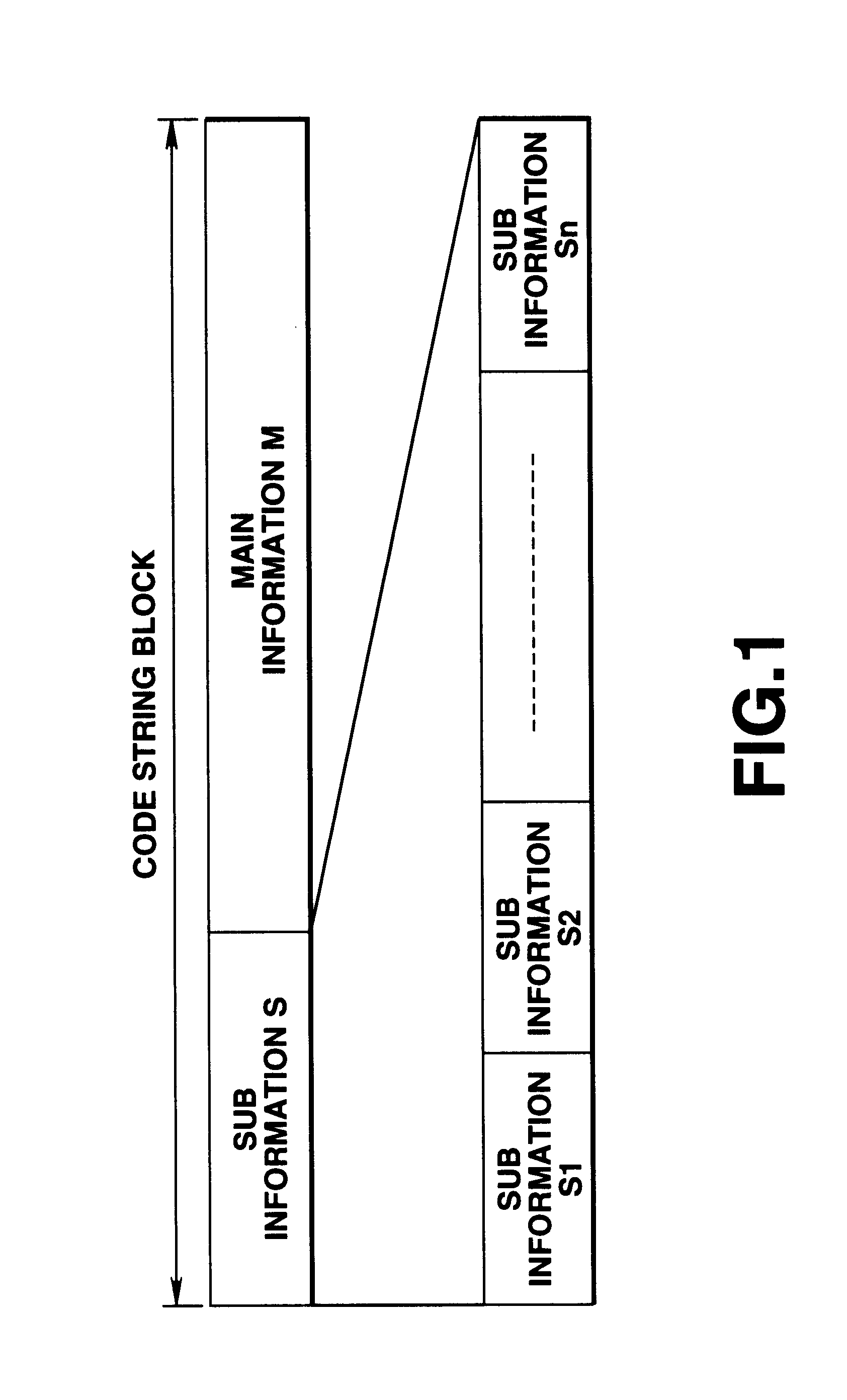
Then, a code string having a different length in accordance with a selected compression rate is cut out from the leading part of the code string block of each unit time, thus enabling regeneration of a code string of a different length. Therefore, a code string having a changed compression rate can be generated at a high speed with a small quantity of operation or a simple structure.

Problems solved by technology

However, since the masking effect is not utilized auditorily, the actual sense of noise is not optimum.
In this technique, however, since bit allocation is fixed, a satisfactory characteristic value is not obtained even when characteristics are measured with a sine-wave input.
Therefore, the conventional method is not suitable for processing which requires high-speed operation, for example, real-time processing for converting the compression rate.

Method used


Image

  • Coding device, coding method, decoding device, decoding method, program recording medium and data recording medium
  • Coding device, coding method, decoding device, decoding method, program recording medium and data recording medium
  • Coding device, coding method, decoding device, decoding method, program recording medium and data recording medium

Examples


Embodiment Construction

A preferred embodiment of the coding device and method according to the present invention will now be described with reference to the drawings. As a matter of course, the description of the embodiment is not intended to limit each means.

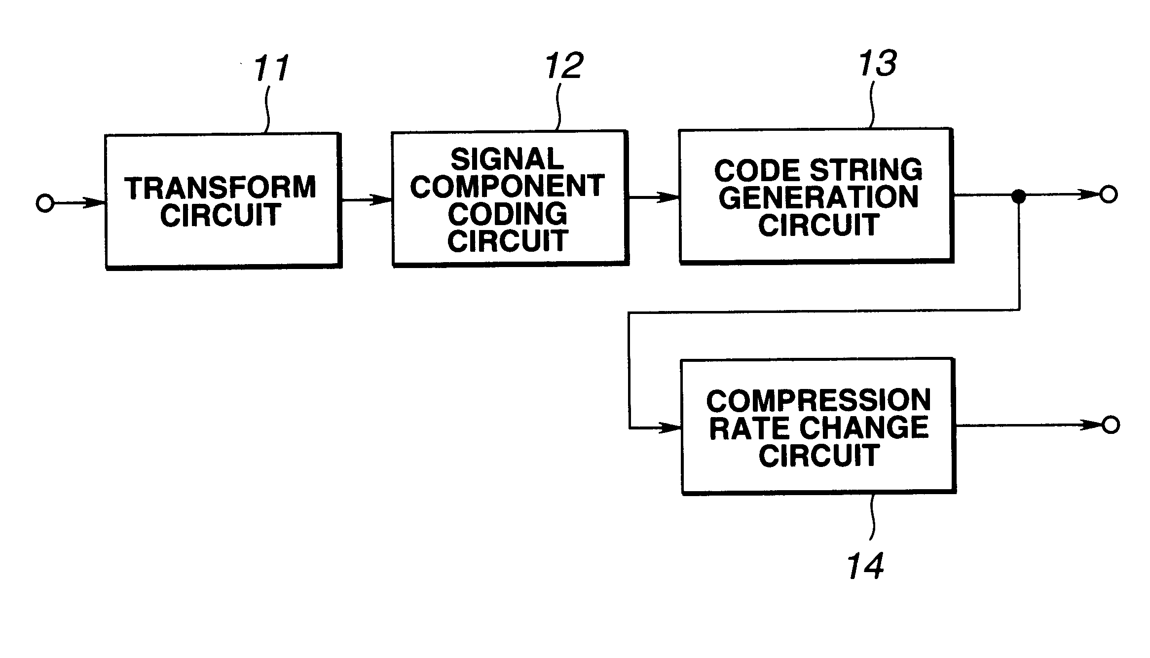
In this embodiment, an audio coding device for coding an audio signal and outputting a compressed code string is employed. This audio coding device has a transform circuit 11 for converting an audio signal to spectral components, a signal component coding circuit 12 for coding the spectral components from the transform circuit 11, a code string generation circuit 13 for generating a code string block of each unit time from the coded data from the signal component coding circuit 12, and a compression rate change circuit 14 for changing, if necessary, the compression rate of the code string from the code string generation circuit 13, as shown in FIG. 2. Normally, the code string from the code string generation circuit 13 is outputted as it is. However,...


PUM


Abstract

A signal component coding circuit codes spectral components from a transform circuit for converting an audio signal to spectral components. A code string generation circuit generates a code string block of each unit time from the coded data from the signal component coding circuit. A compression rate change circuit changes the compression rate of the code string from the code string generation circuit, if necessary. For example, when the compression rate needs to be changed because of a change of the transmission capacity of a transmission line, the compression rate change circuit extracts codes of respective signal components from the code string, if necessary, and thus generates a code string having a changed compression rate. With such a structure, it is possible to solve the problem that processing to be carried out at a high speed such as real-time processing of compression rate change cannot be suitably carried out since an operation scale substantially similar to that of decoding and coding of an acoustic waveform signal is required in generating a code string having a changed compression rate from a code string outputted from a coding device.

Description

TECHNICAL FIELDThis invention relates to a coding device and method for generating a code string by changing the compression rate of a code string generated by code string generation processing in accordance with limitation of the capacity of a transmission line or the like. The invention also relates to a decoding device and method for decoding a code string having the compression rate changed in accordance with the coding device and method. The invention also relates to a program recording medium for recording the coding method and the decoding method as software programs. The invention further relates to a data recording medium in which a code string having the compression rate changed in accordance with the coding method is recorded.BACKGROUND ARTThere are various techniques of high-efficiency coding of audio signals (including speech signals). For example, there is known a subband coding (SBC) technique, which is a non-blocked frequency subband coding system for splitting audio...

Claims


Application Information

Patent Timeline
IPC IPC(8): G10L19/00G10L19/02
CPCG10L19/02G10L19/167G10L19/0204G10L19/035G10L19/24
Inventor KOIKE, TAKASHIIMAI, KENICHITSUJI, MINORU
Owner SONY CORP
Learn More