Pressing tool apparatus and control method

a technology of tooling and control method, applied in the direction of basic electric elements, electric devices, line/current collector details, etc., can solve the problems of difficult to visibly recognize, increased accident risk of working tools, and many accidents at work

Inactive Publication Date: 2003-12-16
AG VON ARX
View PDF14 Cites 34 Cited by
  • Summary
  • Abstract
  • Description
  • Claims
  • Application Information

AI Technical Summary

Problems solved by technology

If the degree of the pressing is only just outside the tolerance limit, then it is difficult to visibly recognize.
A pressing tool apparatus is a working apparatus which has an increased accident risk.
Already, many accidents have occurred at work because the pincers are accelerated away in an uncontrolled manner and the fork-like receiver is spread open and deformed.
Also when the clamping pincer is correctly held in the pressing tool apparatus, this alone still does not ensure a perfect pressing of the tubular workpiece.
For example, the clamping pincer and its clamping jaws may become dirty, and thus a sufficient closure of the clamping pincer is not achieved or the dimensioning of the applied connecting sleeve or pressing sleeve does not correspond to the dimension which is envisaged for the corresponding pincer.
Since these pressing tools are often used on building sites, it is difficult to not dirty the clamping pincer.
Such contamination then often leads to interruptions of the electronic transfer and thus to erroneous information.

Method used


Image

  • Pressing tool apparatus and control method
  • Pressing tool apparatus and control method
  • Pressing tool apparatus and control method

Examples


Embodiment Construction

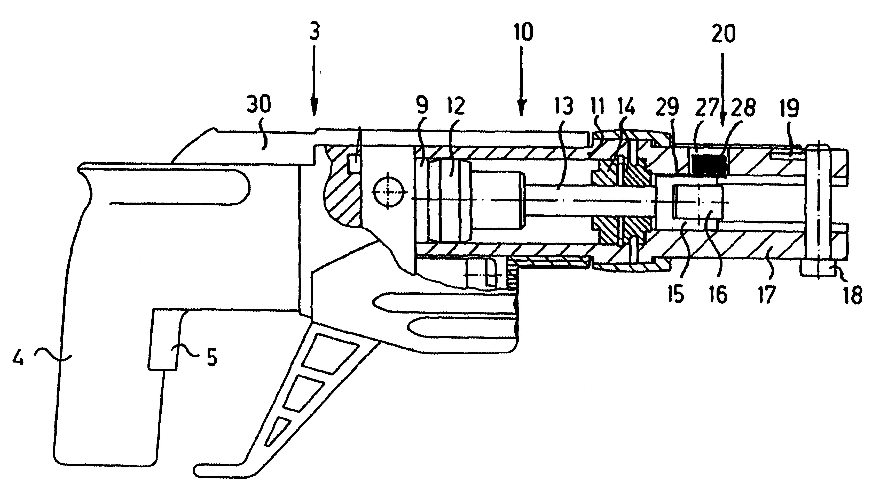
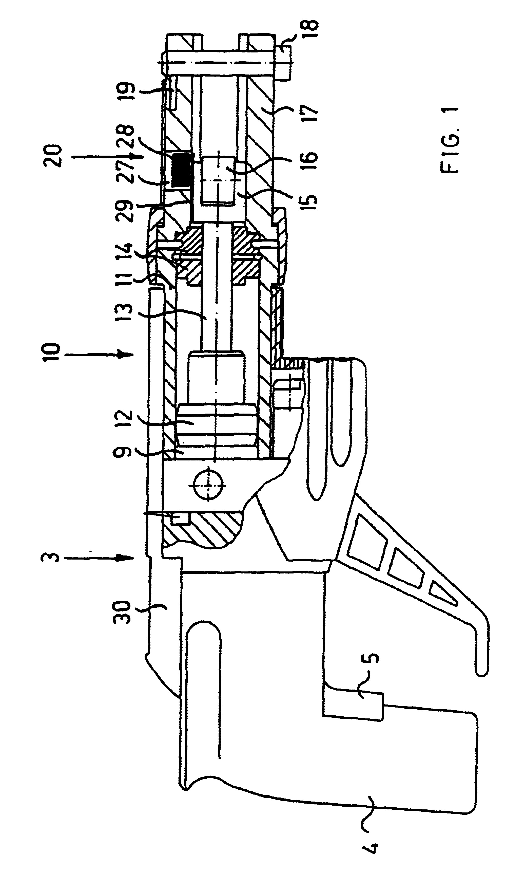
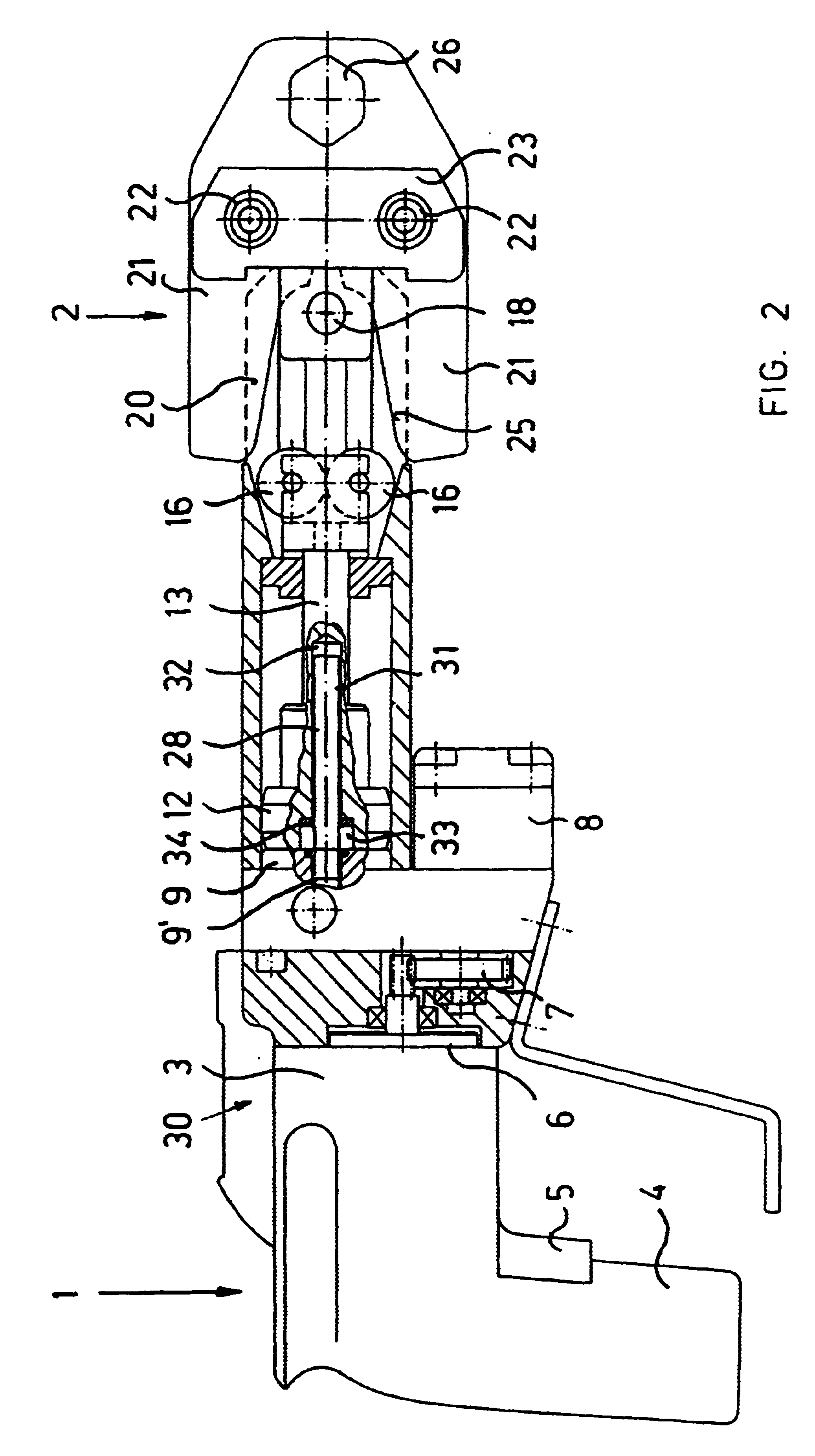
FIG. 1 only shows a pressing tool apparatus 1, while FIG. 2 shows the pressing tool apparatus 1 and an applied clamping pincer 2. The pressing tool apparatus 1 comprises an electro-hydraulic apparatus which is formed as a pistol. The apparatus 1 has a housing 3 with a grip 4. On the grip 4 is arranged a trigger switch 5 via which a pressing procedure is triggered. The electromotoric drive 6 accommodated in the housing 3, via a gear 7, acts on a hydraulic pump 8 which presses hydraulic oil from a storage supply into the cylinder and thus moves the piston.

The piston / cylinder unit is indicated as element reference numeral 10 and comprises a cylinder 11 and a piston 12 movable within the cylinder 11. On the piston 12 there engages a piston rod 13 which is led through a two-part bearing 14. At the end lying opposite the piston 12 on the piston rod 13 there is arranged a roller holder 15. The roller holder 15 has a yoke shape in which there are mounted two rollers 16. An extension of the ...


PUM

PropertyMeasurementUnit
pressureaaaaaaaaaa
displacementaaaaaaaaaa
voltageaaaaaaaaaa

Abstract

A pressing tool apparatus with a clamping pincer and a sensory mechanism that permits a measurement of a displacement which the piston covers with the closure procedure of the clamping pincer. With the first closure of the clamping pincer, without a pressing, there results a nominal displacement value which is realized by a displacement sensor and a ring magnet. Electronics in the housing store a measured nominal value and compares it to subsequent closure procedures with a pressing, accounting for programmable tolerance values. Pressings within a permitted range or outside the range are suitably displayed.

Description

1. Field of the InventionThis invention relates to a method for controlling an electrically operated pressing tool apparatus for pressing coupling elements with a clamping pincer. This invention also relates to a pressing tool apparatus used according to the method of this invention.2. Description of Related ArtPressing tool apparatus of the above mentioned type are used for pressing coupling elements, such as press sleeves, press fittings, connecting sleeves, and tube sections which are inserted into one another. The pressing tool apparatus includes a clamping pincer with clamping jaws which form a pressing space for receiving the coupling element to be pressed. The pressing pressure required for the pressing can be delivered by a hydraulic drive.After each pressing, the pressing tool should be checked whether the coupling element has been pressed to the desired extent or whether the pressing force was too great or too small. The testing is visibly controlled. If the degree of the ...

Claims


Application Information

Patent Timeline
Patent Type & Authority Patents(United States)
IPC IPC(8): B25B27/02B25B27/10H01R43/042H01R43/04
CPCB25B27/10H01R43/0428
Inventor AMHERD, RENE
Owner AG VON ARX
Why Eureka
Try Eureka