Pivoting type latch for removable electronic devices

a technology of electronic devices and latches, which is applied in the direction of coupling device connections, instruments, mechanical devices, etc., can solve the problems of affecting the service life of the latch device, the service time and expense of the computer or server, and the numerous related costs, so as to prevent damage to any related expensive devices, the effect of reducing the inconvenience and expense of replacing broken

Inactive Publication Date: 2003-12-23
LUMENTUM OPERATIONS LLC
View PDF9 Cites 58 Cited by
  • Summary
  • Abstract
  • Description
  • Claims
  • Application Information

AI Technical Summary

Benefits of technology

It is a still further object of the invention to minimize the inconvenience and expense of replacing broken or damaged latch members.
It is still an additional object of the invention that the removable and replaceable latch be the weakest component in the latching system to protect the transceiver module and the electronic system from damage from excessive forces applied to a communications data cable.
It is still another object of the invention to eliminate the need for skilled ser...

Problems solved by technology

A very significant problem concerning one proposed design for the interconnection interface relates to the latch itself, which retains the transceiver module within the computer housing and connects by the interconnection interface within the communication port.
The latch device, where it is accessible and operable outside the computer housing, is subject to impact or large forces such as sufficient pulling of the connected cable to break the latch.
Should the projecting latch member be broken, the computer or server may require significant service time and expense to return the communications or network connection to a functional and reliable condition.
Disruption to the service of the computer or server, while the sys...

Method used


Image

  • Pivoting type latch for removable electronic devices
  • Pivoting type latch for removable electronic devices
  • Pivoting type latch for removable electronic devices

Examples


Embodiment Construction

The following description of the invention is made for purposes of disclosure of the best mode of the preferred embodiment and is not intended to limit the invention in any manner or limit the attached claims which define the scope of protection afforded the invention.

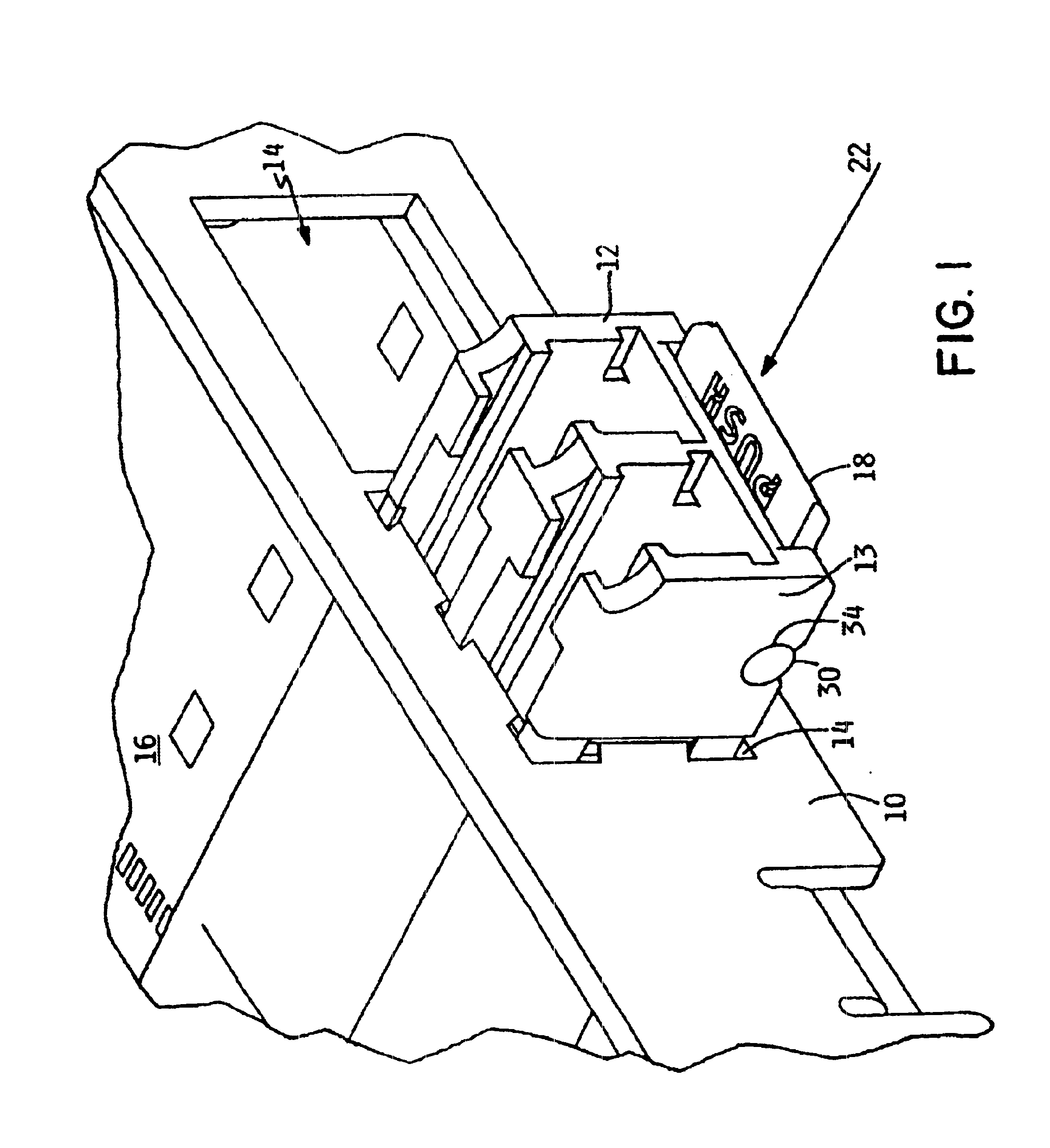
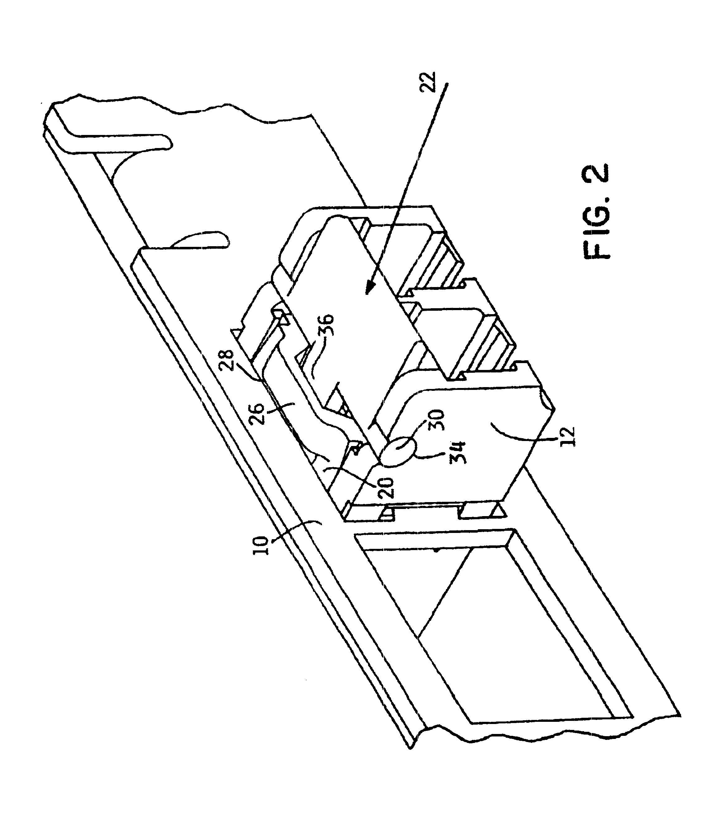
Initially for purposes of disclosure of the invention, reference is made to FIG. 1 where a bezel 10 or housing member 10 of an electronic system housing (not shown) is illustrated with a transceiver module 12 inserted into a communications port 14, which is ready to receive connectors (not shown) to connect the transceiver module 12 to a communication network which, in turn, interconnects a plurality of computers and / or servers.

The transceiver module 12 is retained within the electronic system bezel 10 by a latch arrangement. The transceiver module 12 must be readily removable to permit other similar modules to be inserted and connected. The transceiver modules 12 are interchangeable as required depending upon the type...


PUM


Abstract

A push-to-release latching mechanism for retaining a transceiver module in a communication port of a computer or server is provided with a beam spring structure for positional restoration of the latch member, and the latch is supported and moveable relative to the host transceiver module. The latch member may be formed to include camming surfaces that facilitate the insertion of the transceiver module into a communication port and mate with a guide rail and connector resident in a communication port. The latch member may be adapted to latch with a rigid latch bar or a cantilevered spring. Additionally, the latch may be formed with a camming surface which insures that the latch is displaced to a latching position whenever network cables are connected to the transceiver module by camming the latch into the secure, latched position and subsequently preventing the latch from moving to an insecure or unlatched position. The latch member is pivotally supported on the transceiver module in a shaft/journal arrangement and thus is removed from the communication port whenever the transceiver module is removed, thereby preventing the latch from projecting from the communication port and being subject to damage. The latch member may be formed with a living hinge to provide a pivot axis and one end of the living hinge may be attached to a electronic module chassis or to a support structure which may be mated with a electronic module chassis for easy replaceability.

Description

CROSS REFERENCE TO RELATED UNITED STATES PATENT APPLICATIONSThe following are related co-pending United States patent applications:REMOVABLE SMALL FORM FACTOR FIBER OPTIC TRANSCEIVER MODULE CHASSIS, Serial No. 09 / 489,870, filed Jan. 20, 2000, by Scott M. Branch, David P. Gaio and William K. Hogan;REMOVABLE LATCH AND BEZEL EMI GROUNDING FEATURE FOR FIBER-OPTIC TRANSCEIVERS, Serial No. 09 / 410,786, now U.S. Pat. No. 6,485,322, filed Oct. 1, 1999, by Scott M. Branch, David P. Gaio and William K. Hogan;REMOVABLE SMALL FORM FACTOR FIBER OPTIC TRANSCEIVER MODULE AND ELECTROMAGNETIC RADIATION SHIELD, Serial No. 09 / 489,184, now U.S. Pat. No. 6,335,869, filed Jan. 20, 2000, by Scott M. Branch, David P. Gaio and William K. Hogan, which are incorporated herein in their entireties by this reference.This invention relates to retaining mechanisms, and more specifically, to the latching mechanism utilized to retain an electrical interconnection and data signal conversion device in an installed cond...

Claims


Application Information

Patent Timeline
IPC IPC(8): E05C3/14E05C3/00G02B6/42H01R13/629E05C19/00E05C19/06
CPCE05C3/14H01R13/62933G02B6/4292E05C19/06H01R12/7005G02B2006/4297Y10T292/0934Y10T292/1061
Inventor BRANCH, SCOTT MICHAELDAY, LELAND L.GAIO, DAVID PETERHANLEY, MICHAEL FRANCISHOGAN, WILLIAM K.
Owner LUMENTUM OPERATIONS LLC
Why Eureka
Try Eureka