Method for determining the angular position of a rotative part which performs a rotational movement

a technology of rotational movement and angular position, which is applied in the direction of transmission systems, instruments, transportation and packaging, etc., can solve the problems of affecting the manner of operation and not allowing a series mass production utilization of this method

Inactive Publication Date: 2003-12-30
DAIMLER AG
View PDF10 Cites 19 Cited by
  • Summary
  • Abstract
  • Description
  • Claims
  • Application Information

AI Technical Summary

Benefits of technology

In the presented method, advantageously, a contact-less position detection (determination of the angular position) of the rotative part carrying out rotational movements can be achieved, without hereby causing mechanical frictions, rotational moments, or noises to arise, or mechanical parts to be moved. The position detection can be carried out over plural rotations of the movable part with a high signal amplitude, whereby the detection range is only limited by the rotating range of the winding band, and whereby a high interference security, especially relative to position variations of the winding band in the housing as well as relative to external electromagnetic couplings, is achieved.

Problems solved by technology

It is disadvantageous in this context, that the inductivities or inductivity variations of the winding band that are to be measured are extremely small and thus parasitic inductivities (for example those from supply lines) falsify the inductivity measurement, that a non-linear relationship between the rotational path or travel and the inductivity results, and that a separate return line is necessary between the beginning and the end of the winding band that forms the inductivity, whereby this return line hinders the uninterfered movement of the winding band and of the rotative part and thus impairs the manner of operation and does not allow a series mass production utilization of this method.

Method used


Image

  • Method for determining the angular position of a rotative part which performs a rotational movement
  • Method for determining the angular position of a rotative part which performs a rotational movement

Examples


Embodiment Construction

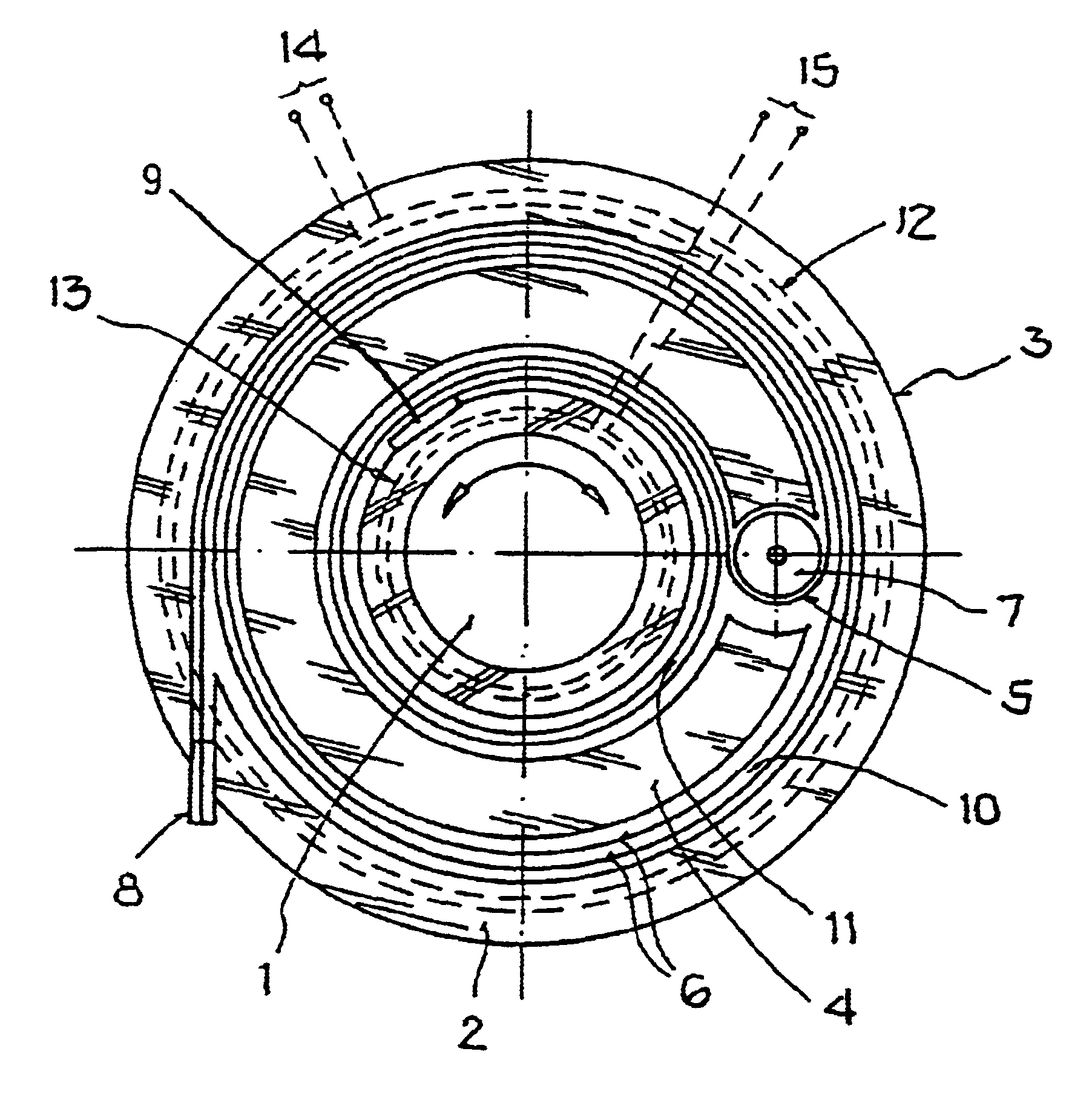
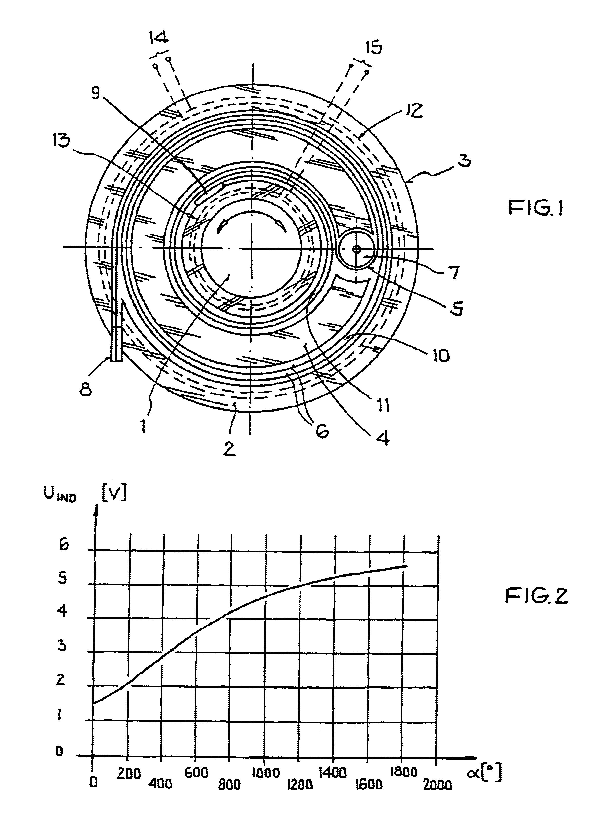
In this context, a schematic illustration of the arrangement of the winding band is shown in a plan view in FIG. 1, and a measuring diagram with the magnetic coupling as a function of the rotational angle is illustrated in FIG. 2.

According to FIG. 1, there is provided a winding band 5 that is arranged in a housing 3 and applied on a carrier 4, for the determination of the angular position of the rotative part 1 carrying out rotational movements with respect to a fixed stationary part 2. The winding band 5 consists of parallel guided electrical conductors 6. The necessary length of the winding band 5 prescribed by the rotational movement is limited by the deflection roller 7 and split into an outer part 10 and an inner part 11. The two electrical contacts or connections 8, 9 of the winding band 5 are provided for the signal transmission and for the electrical connection to the fixed stationary part 2. Signal lines (for example a plug contact) can be connected to the electrical contac...


PUM


Abstract

A winding band including at least one conductor is arranged on a carrier in a housing, and is coupled to a rotative part, so that a wound-up length of a wound-up portion of the winding band varies corresponding to a rotational movement of the rotative part. At least one measuring inductor is arranged proximate to the wound-up portion of the winding band. The angular position of the rotative part is determined by detecting an electromagnetic field coupling between the measuring inductor and the wound-up portion of the winding band, and evaluating the amplitude, frequency and / or phase of an induced voltage arising in the inductor due to the coupling.

Description

The invention relates to a method for determining the angular position of a rotative part carrying out rotational movements.BACKGROUND INFORMATIONIN many fields of application, especially in the field of motor vehicles, in automation technology, measurement technology, control technology, and signal transmission technology, or in the field of machine tools, the rotational angle and therewith the angular position of parts carrying out rotational movements must be determined. For motor vehicles, for example, the steering wheel angle or the steering wheel position is helpful or indispensable as a measure for the position of the steering wheel in many applications, especially for the operation of driving dynamic systems (for example adaptive damping systems, all wheel drive, rear axle steering), driving assistance systems (for example separation distance warning systems, separation distance control systems) or navigation systems. For detecting the angular position, in addition to magnet...

Claims


Application Information

Patent Timeline
Patent Type & Authority Patents(United States)
IPC IPC(8): B62D15/00B62D15/02G01D5/20G01B7/30G01B7/00G01D5/12
CPCB62D15/02G01D5/2073G01B7/30G01B7/003
Inventor GLEMSER, ANDREASJOCHUM, HERBERTSCHAUER, LOTHARSERR, HELMUT
Owner DAIMLER AG
Why Eureka
Try Eureka