Method of repointing a reflector array antenna

a reflector array and array antenna technology, applied in the direction of antennas, electrical equipment, antennas, etc., can solve the problems of pointing error, angular difference, pointing error, etc., and achieve the effect of sufficient accuracy

Inactive Publication Date: 2003-12-30
ALCATEL LUCENT SAS
View PDF16 Cites 4 Cited by
  • Summary
  • Abstract
  • Description
  • Claims
  • Application Information

AI Technical Summary

Benefits of technology

The object of the present invention is therefore to provide a method of repainting reflector array antennas that does away with the use of complex, costly, and bulky motors, but nevertheless provides sufficient accuracy, as required by geosynchronous satellites in particular.

Problems solved by technology

Pointing errors occur during operation of satellites.
Generally speaking, a pointing error is the angular difference between the theoretical position of the antenna (and / or its reflector) and its actual position on each axis of a three-dimensional system of axes.
Pointing errors are linked in particular with the angular instability of the position of the satellite, with errors in the position of the antenna relative to the satellite, and with internal deformation of the antenna, such as thermal deformation of the reflector.
The first two sources of error are the dominant ones and lead to an overall pointing error for all the spots formed by the antenna.
The satellite has attitude control systems, but these achieve accuracy of the order of only one tenth of a degree, which is insufficient with geosynchronous satellites in which the coverage is provided by multiple narrow beams.
It is therefore bulky and costly.
Also, modifying the position of the reflector relative to the array changes the configuration of the antenna, which can degrade performance (in particular focusing).
Furthermore, that solution is not sufficiently accurate for large reflectors.

Method used


Image

  • Method of repointing a reflector array antenna
  • Method of repointing a reflector array antenna
  • Method of repointing a reflector array antenna

Examples


Embodiment Construction

In all the figures, common items carry the same reference numerals.

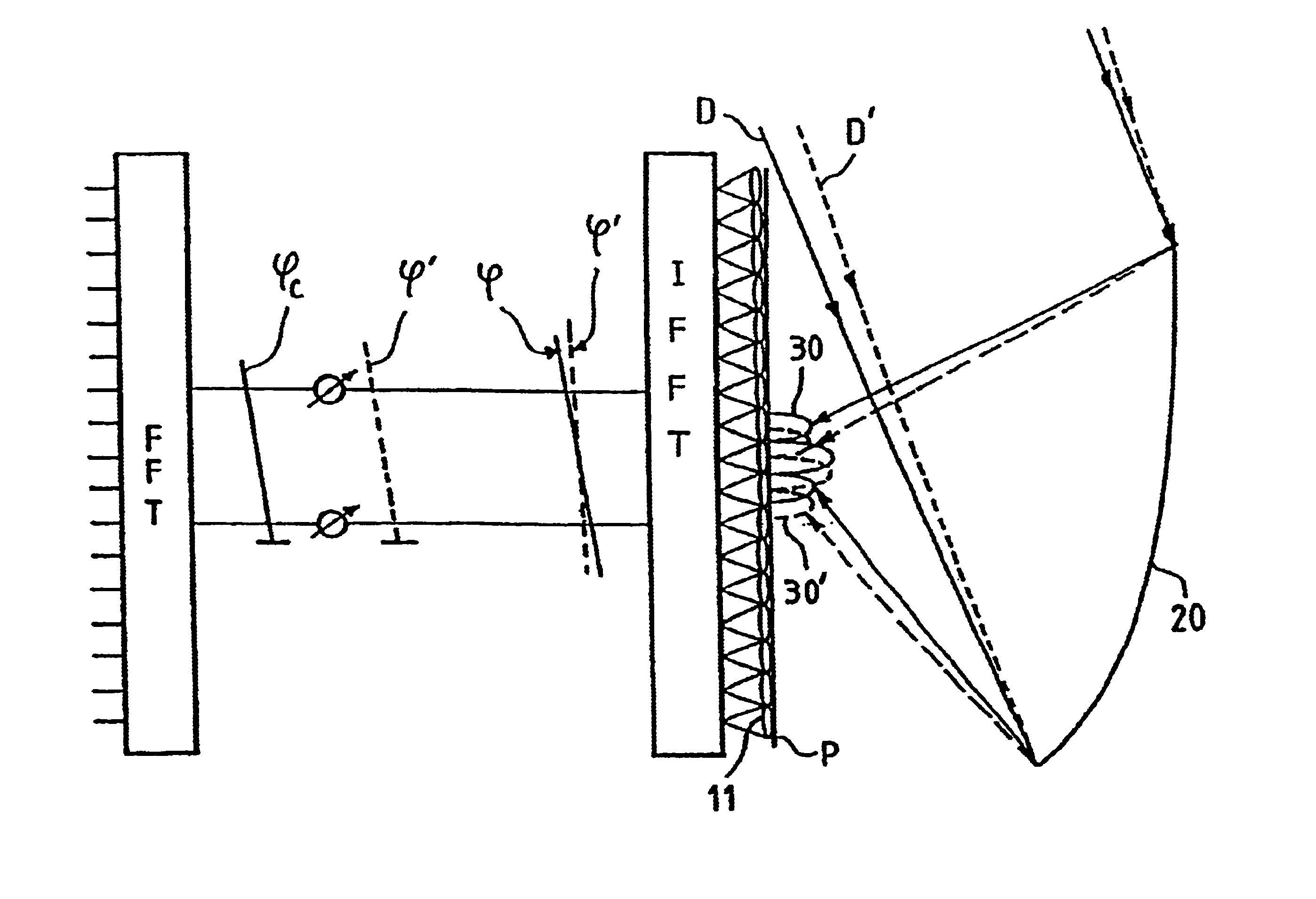
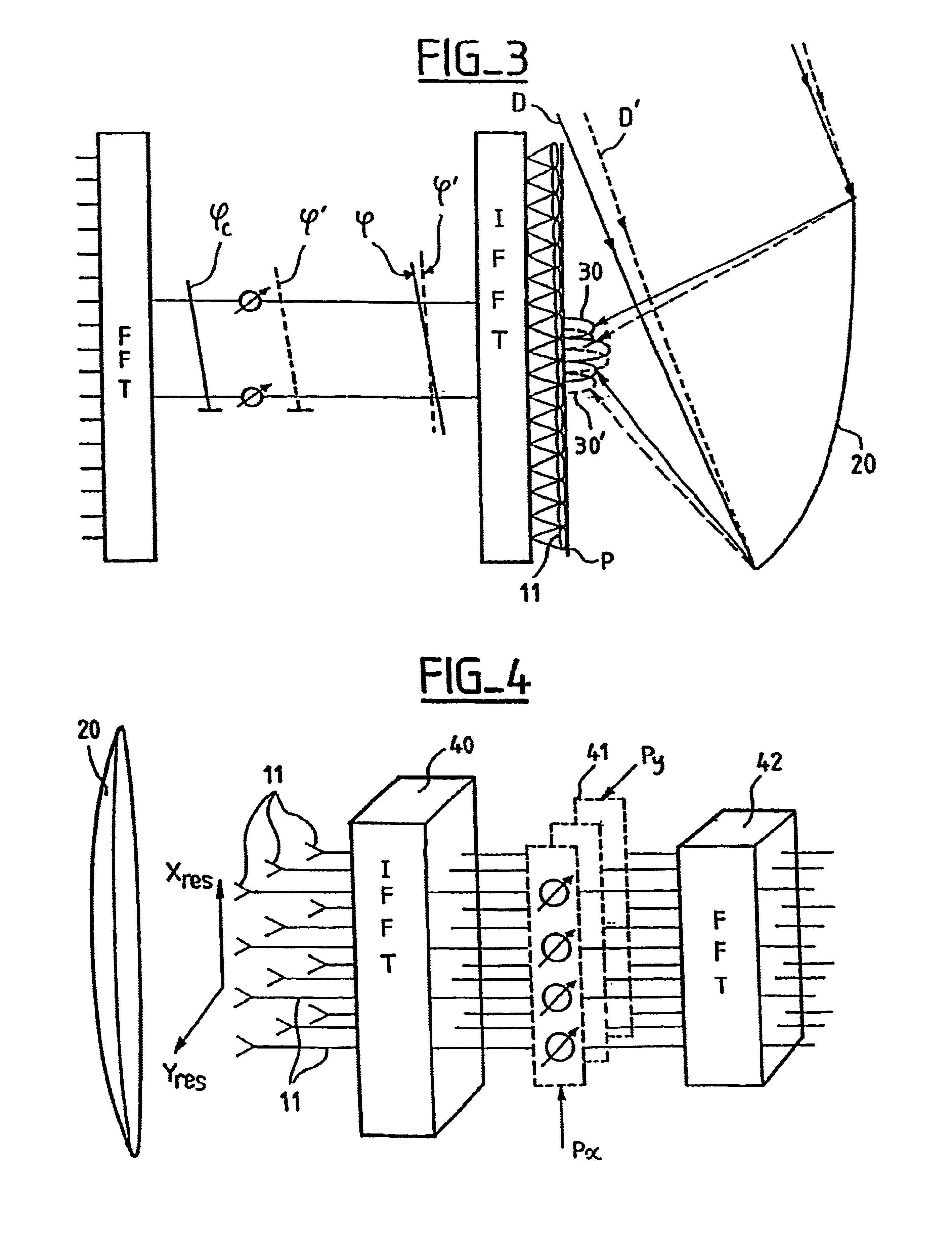
As a general rule, beamforming networks have as many inputs as there are radiating elements and as many outputs as there are beams to be formed. There are two types of beamforming: analog beamforming, using a radio frequency medium, and digital beamforming (also referred to as computation beamforming), in which the signal received by the radiating elements is formatted, and then sampled, and then processed by digital processors in order to extract the wanted information from it.

The remainder of the description refers throughout to a receive antenna, but everything to be explained is equally applicable, mutatis mutandis, to transmit antennas, which differ from receive antennas mainly in their practical implementation.

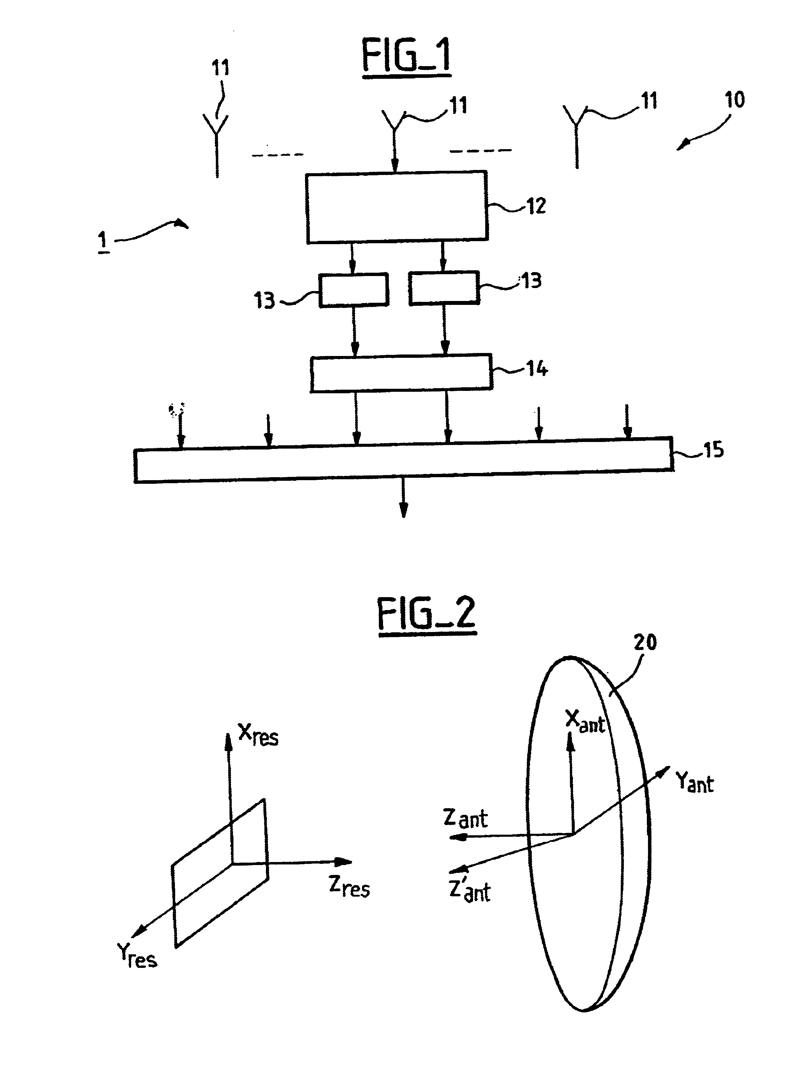
FIG. 1 shows a computation beamforming antenna 1 comprising the following components:

an array 10 of radiating elements 11,

downstream of each radiating element 11 (or of each group of radiating elements), ...


PUM


Abstract

The present invention relates to a method of repainting a reflector array antenna comprising a plurality of radiating elements and being of the type that forms beams by computation, in which method each signal received by said antenna is sampled.The method comprises the following operations:estimating the depointing of the radiation pattern of the antenna to obtain a phase shift matrix,computing the discrete inverse Fourier transform of the signal samples supplied by the radiating elements,multiplying the phase shift matrix by the inverse Fourier transform of the sampled signal, andcomputing the discrete direct Fourier transform of the product of the phase shift matrix and the inverse Fourier transform of the sampled signal.

Description

The present invention relates to a method of repainting a reflector array antenna, especially a reflector array antenna used on board a geosynchronous satellite.Array antennas form one or more radiation patterns using a set of individual sources whose signals are combined by a digital or analog beamforming network. Array antennas can therefore form a plurality of patterns simultaneously, i.e. multibeam coverage, by applying a plurality of different feed laws. Multibeam coverage is frequently used in telecommunications, especially in systems using geosynchronous satellites.Given the very high altitude of geosynchronous satellites, the multibeam coverage of the array antennas used on board them is obtained by using very narrow beams, typically having a beam width of the order of one degree. For patterns that are this directional, small amounts of depointing can cause strong variations in the power radiated in a given direction. Consequently, it is important for the beams to be pointed...

Claims


Application Information

Patent Timeline
Patent Type & Authority Patents(United States)
IPC IPC(8): H01Q3/30H01Q3/40H01Q3/26H01Q25/00H01Q1/28H01Q19/17
CPCH01Q3/2658H01Q25/008H01Q25/007H01Q3/40
Inventor GUIRAUD, CECILELEGAY, HERVEBOUCHERET, MARIE-LAURE
Owner ALCATEL LUCENT SAS
Why Eureka
Try Eureka