Railway axle hub unit

a technology for axle hubs and axles, which is applied in the direction of bearings, roller bearings, vehicles, etc., can solve the problems of reducing the safety of the vehicle, failure of the bearing, and excessive play between the components of the axl

Inactive Publication Date: 2004-01-06
SKF IND SPA
View PDF12 Cites 32 Cited by
  • Summary
  • Abstract
  • Description
  • Claims
  • Application Information

AI Technical Summary

Benefits of technology

Another object of the present invention is to provide a continuous and real time monitoring of the operating condition of the bearing to obtain real time information concerning the variation of the defect in time, so that it is possible to intervene with urgency for severe failures, or delay intervention depending on the gravity of the detected failure, or consider the opportunity of not intervening, for example when an operation defect is stabilised or is stabilising.

Problems solved by technology

Mechanical deterioration of the axle supporting bearings, besides adversely affecting the operational performance of the axle, also reduces the safety of the vehicle and may lead to the failure of the bearing, with catastrophic consequences such as derailment.
manufacturing or assembling defects of the bearing, which provoke an excessive play between its components (inner and outer raceways, rolling bodies, retaining cages, sealing devices, shoulders defining the axial position of the bearing with respect to the axle); cracks or spalls due to fatigue; local pitting due to an electrical current passing through the bearing; rust marks;
flats in the rolling surface of a wheel due to the wheel being locked while the railway vehicle is travelling; excessive wear of the wheel profile in the rail contact zone;
Up to now methods of checking the conditions of the bearings have been limited to periodical maintenance interventions.
It will be understood that this way of proceeding first of all involves high costs of labour and passive costs for leaving the vehicle unused, but above all it does not allow to predict or detect the occurrence of failures in time before the bearing is so deteriorated to represent a condition of potential danger.
Therefore, there is the risk of continuing to use a defective bearing or wheel for prolonged periods till the moment set by the maintenance schedule for replacement.

Method used


Image

  • Railway axle hub unit
  • Railway axle hub unit
  • Railway axle hub unit

Examples


Embodiment Construction

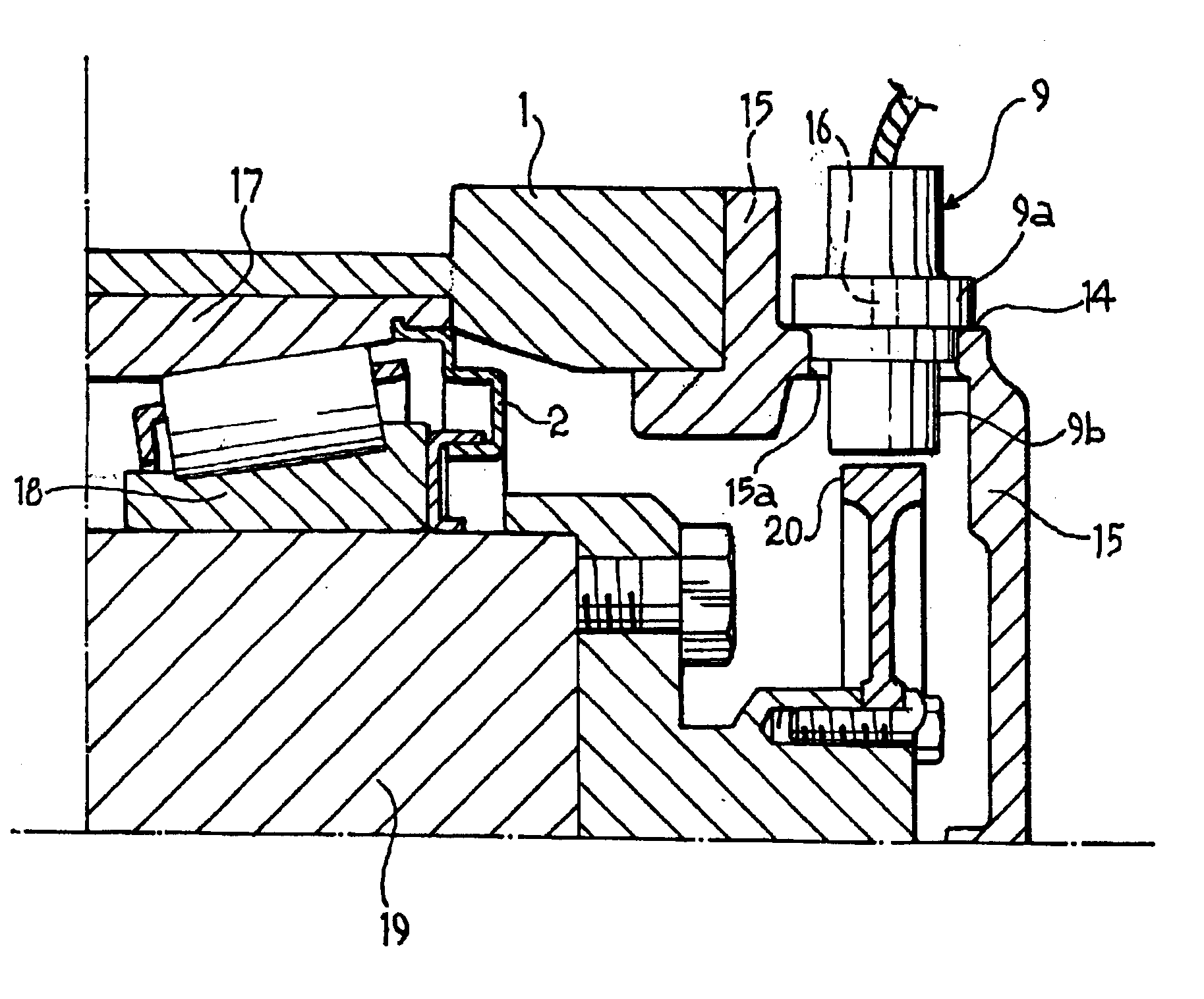
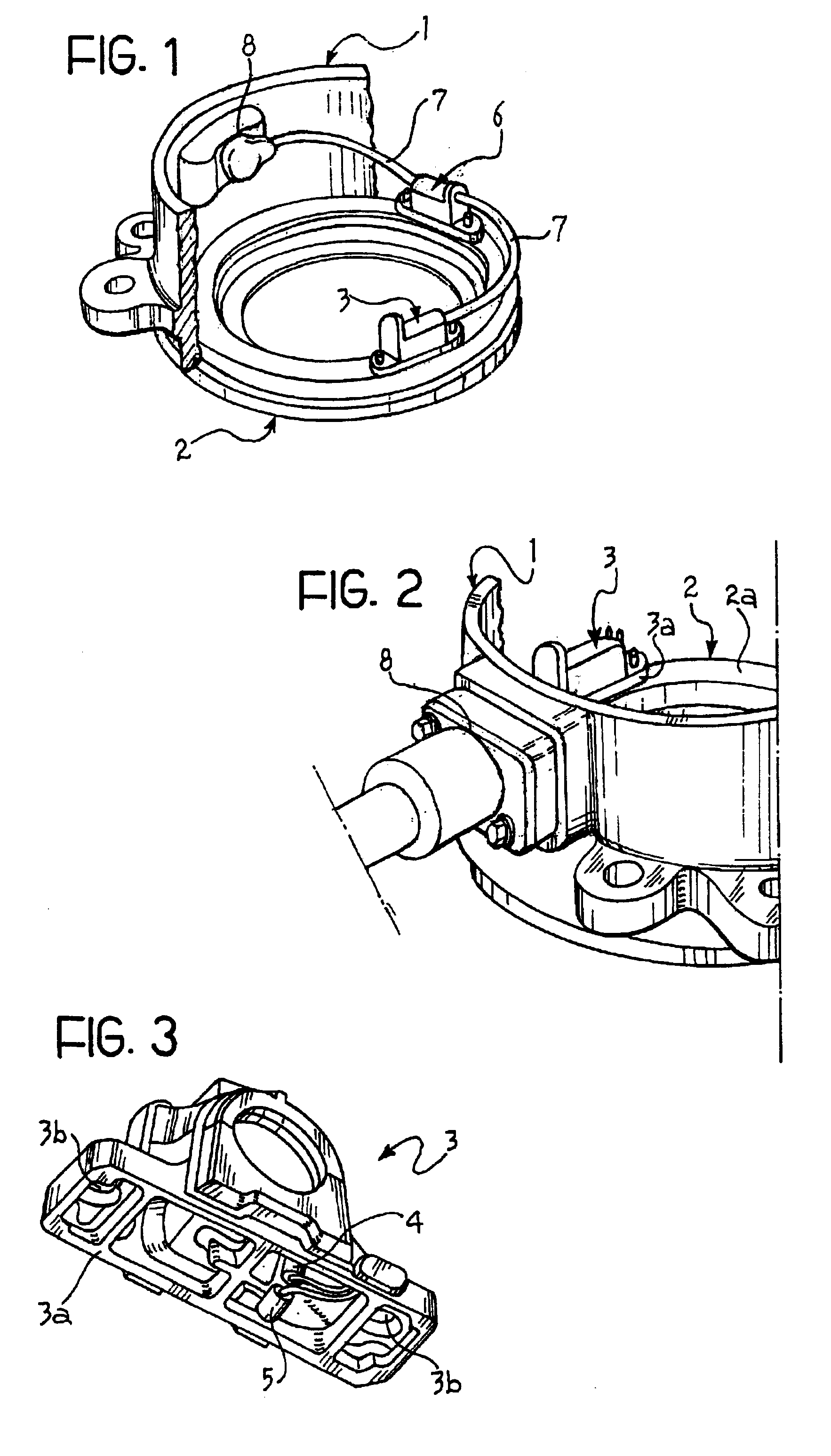
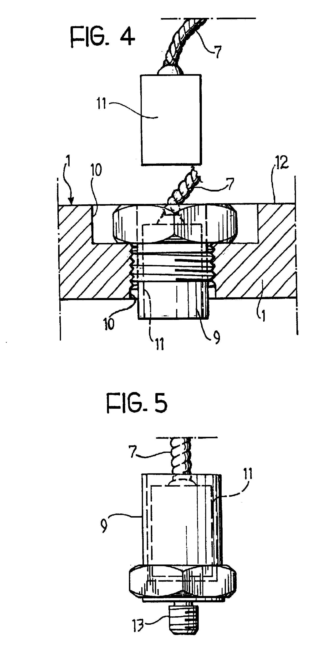
Referring initially to FIG. 1, numeral 1 designates overall a substantially cylindrical bearing housing fixable in known manner to a railway vehicle for supporting a rolling contact bearing housed therein and not shown for simplicity.

A metal annular insert 2, adapted for sealing the bearing from the outboard side, is press fitted onto the radially outer race (indicated 17 in FIG. 6) of the axle bearing. Preferably, the sealing insert 2 is made of cold forged steel plate about 2 mm thick.

With reference also to FIG. 3, in accordance with the invention, mounted on the sealing insert 2 is a sensor body 3 containing a bi-directional accelerometer device comprised of a first accelerometer 4 oriented in the vertical direction and a second accelerometer 5 oriented in the horizontal axial direction.

Advantageously, the sensor body 3 is positioned on the sealing insert 2 at a position vertically aligned with the axis of rotation of the bearing, where the vibrations are more intense. Preferably...


PUM

PropertyMeasurementUnit
thickaaaaaaaaaa
axis of rotationaaaaaaaaaa
temperatureaaaaaaaaaa

Abstract

A railway axle hub unit of the type including an axle box housing (1) for supporting a bearing, is provided with a sensor body (3, 9) containing sensors (4, 5) for detecting vibration in the vertical direction and the horizontal axial direction. The sensor body is mounted onto a stationary support element (2, 1, 15) rigidly secured to the bearing, preferably an annular sealing insert. The sensors perform monitoring of the operation condition of the hub unit by generating and transmitting signals indicative of the detected level of vibration to an electronic processing unit mounted on board of the railway vehicle or the train. The processing unit is capable of signalling in real time an impending failure and / or a damaged condition associated with the monitored hub unit.

Description

The present invention refers to a railway axle hub unit of the type comprising an axle box housing for supporting a bearing.Mechanical deterioration of the axle supporting bearings, besides adversely affecting the operational performance of the axle, also reduces the safety of the vehicle and may lead to the failure of the bearing, with catastrophic consequences such as derailment.The main structural or functional defects which bearings of the above kind or the relative wheel are subject to can be summarised as follows:manufacturing or assembling defects of the bearing, which provoke an excessive play between its components (inner and outer raceways, rolling bodies, retaining cages, sealing devices, shoulders defining the axial position of the bearing with respect to the axle); cracks or spalls due to fatigue; local pitting due to an electrical current passing through the bearing; rust marks;insufficient lubrication of the inner parts of the bearing; polluted or deteriorated lubrica...

Claims


Application Information

Patent Timeline
Patent Type & Authority Patents(United States)
IPC IPC(8): B61F15/00B61K9/00B61F15/20B61K9/12B61K9/04F16C19/36F16C19/52F16C41/00
CPCB61F15/20B61K9/04B61K9/12G01M13/045F16C35/047F16C19/527F16C2326/10F16C19/386F16C19/525F16C41/007
Inventor MORETTI, ROBERTOSEMA, SILVANOGENERO, MATTEO
Owner SKF IND SPA
Why Eureka
Try Eureka