
Spherical connector and supporting rod assembly

a technology of supporting rods and connectors, which is applied in the direction of rod connections, couplings, branching pipes, etc., can solve the problems of increasing the trouble and inconvenience of assembly, reducing the variation of the entire structure of the beam framework, and failing to meet the need for space alternation by the user, etc., to achieve the effect of increasing the application

Inactive Publication Date: 2004-01-06
CHEN CHUNG TENG
View PDF23 Cites 47 Cited by
  • Summary
  • Abstract
  • Description
  • Claims
  • Application Information

AI Technical Summary

Benefits of technology

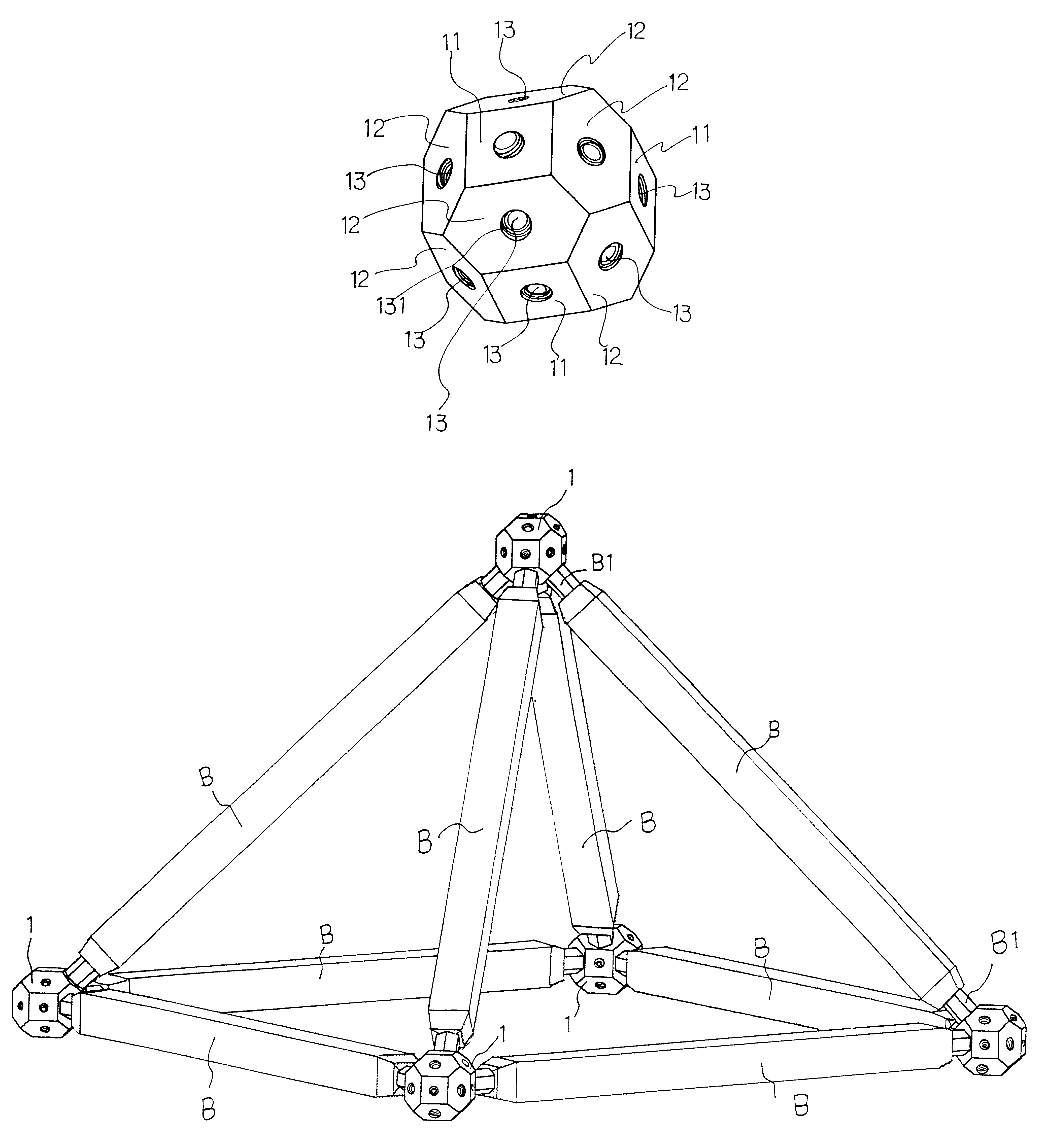
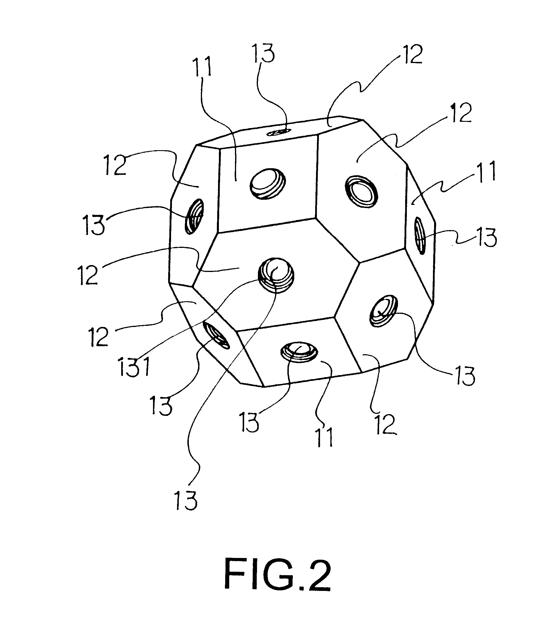
Therefore, the invention herein of a spherical connector and supporting rod assembly, by designing the entire external shape of the spherical connector as a spherical structure of a multi-angular spheroid with multiple tangent planes of six cubical quadrilateral and twelve beveled hexagonal tangent planes connected among the side lines of the six quadrilateral tangent planes, and with mounting holes disposed respectively at the centers of the quadrilateral and the beveled hexagonal tangent planes to make each spherical connector have eighteen mounting holes with included angles pointing at different directions to increase the application of a single spherical connector and to make the structures of all the spherical connector the same for exchangeable connection, has the main objective of not only complying with the needs of specific application, but also being capable of making various applications to meet the requirement of specific assembly for the alternation of different degrees of mounting angles.
Another objective of the invention herein of a self-assembled spherical connector is to use the external design of the polygonal sphere to distinguish the tangent planes of all the mounting holes into the shapes of squares and hexagons to allow the user to quickly identify the positions of desired mounting holes for assembling so as to increase the precision and convenience of assembling.
Yet another objective of the invention herein of a self-assembled spherical connector is to thread the inside of the mounting holes on the spherical joint for the structural need of the supporting rods to provide the fixedly fastening of the threads on the end portion of the supporting rod to enhance the connection strength among all the supporting rods.

Problems solved by technology

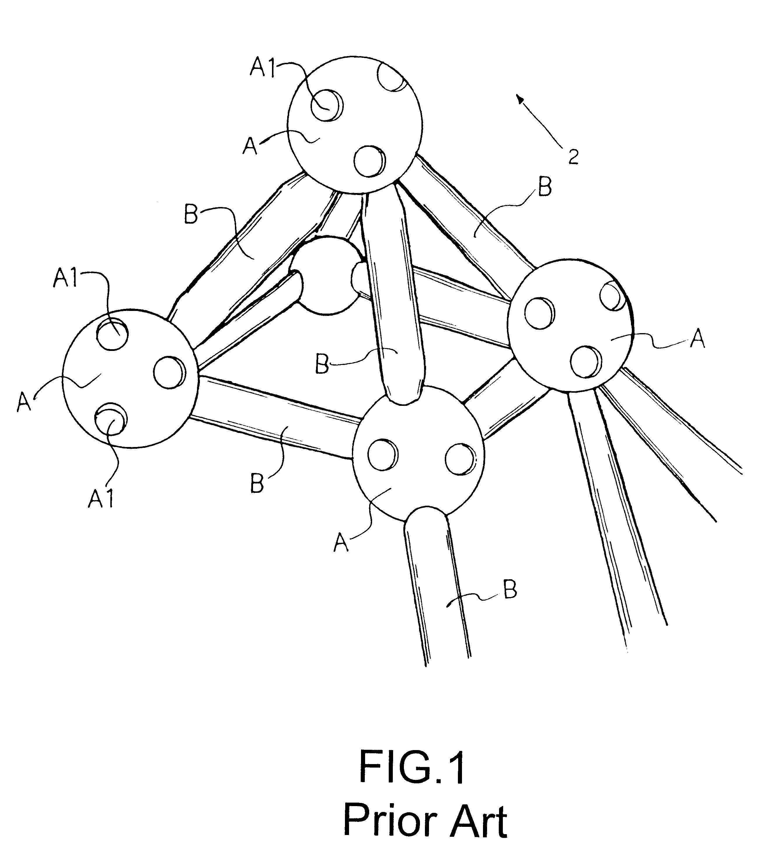
Therefore, every spherical joint with its own specific mounting order and position not capable for exchangeable connection not only reduces the variation of the entire structure of the beam framework, but also fails to meet the need of space alternation required by the user.
Furthermore, the smooth external ball shapes of all the spherical joints make the distinguishing of each mounting hole difficult, that increases the trouble and the inconvenience of assembling.

Method used


Image

  • Spherical connector and supporting rod assembly
  • Spherical connector and supporting rod assembly
  • Spherical connector and supporting rod assembly

Examples


Embodiment Construction

Referring to FIG. 2 of the basic structure of the spherical connector of the invention herein of a self-assembled spherical connector, every spherical connector (1) has the same external structure shape and the same design for the mounting holes (13). Wherein, the entire external shape of the spherical connector (1) is designed as a structure of a multi-angular spheroid with multiple tangent planes. The external sides of the spherical connector 91) has six tangent planes (11) of cubical quadrilaterals with twelve tangent planes (12) of beveled hexagons connected among the side lines of the six quadrilateral tangent planes, and with mounting holes (13) disposed respectively at the centers of the tangent planes of the squares (11) and the beveled hexagons (12) to make each spherical connector (1) have eighteen mounting holes (13) with included angles pointing at different directions to not only increase the application of a single spherical connector (1), but also to comply with the n...


PUM


Abstract

The invention herein of a spherical connector and supporting rod assembly is mainly designed as a structure of a multi-angular spheroid with multiple tangent planes of six cubical quadrilaterals and twelve beveled hexagons, and with mounting holes disposed respectively at the centers of the quadrilateral and the beveled hexagonal tangent planes to make each spherical connector having eighteen mounting holes with included angles pointing at different directions so as to increase the application of a single spherical connector and to make all the spherical connectors have the identical structure for exchangeable connection to not only fully comply with the needs of specific application, but also to be able to make various applications by using the supporting rods pointing at different mounting angles to directly fulfill the specific need of the assembly.

Description

BACKGROUND OF THE INVENTION1. Field of the InventionThe invention herein of a spherical connector and supporting rod assembly mainly provides a spherical connector not limited by the position and the order of assembly but capable of enabling the user to quickly identify the correct mounting holes to be connected with the supporting rods extending to various directions; more especially, every single spherical connector has the same external shape and the same mounting method for the mounting holes and is exhangeable to not only enhance the speed and convenience of assembling, but also reduce the molding cost of manufacturing the spherical connector.2. Description of the Prior ArtAs shown in FIG. 1 of the isometric drawing of the assembled framework of the conventional beam structure, the entire beam framework structure is constructed by a spherical joint (A) connected with the supporting rods (B), wherein the supporting rods (B) are lapped in various directions according to the speci...

Claims


Application Information

Patent Timeline
IPC IPC(8): F16B7/18
CPCF16B7/185Y10T403/347Y10T403/44Y10T403/342
Inventor CHEN, CHUNG-TENG
Owner CHEN CHUNG TENG
Learn More