Method and apparatus for optical time domain reflectometry (OTDR) analysis

Inactive Publication Date: 2004-01-06
AMERICAN TELEPHONE & TELEGRAPH CO
View PDF3 Cites 65 Cited by
  • Summary
  • Abstract
  • Description
  • Claims
  • Application Information

AI Technical Summary

Problems solved by technology

If the core is not properly matched light reflections occur disrupting the communications.
Fiber-optic cable deployed for commercial use may be damaged or have faults.
For example, the glass-like core may crack or fracture under stress or when new pieces of fiber-optic cable are connected together, the light traveling down the glass-like core medium may be inappropriately reflected.
Known faults are points along a cable run where the operator expects to see a discontinuity such as a location where the fiber-optic cable is connected to other fiber-optic cables or equipment.
For example, an operator may establish that a distance between the reference trace and

Method used


Image

  • Method and apparatus for optical time domain reflectometry (OTDR) analysis
  • Method and apparatus for optical time domain reflectometry (OTDR) analysis
  • Method and apparatus for optical time domain reflectometry (OTDR) analysis

Examples


Embodiment Construction

While the present invention is described herein with reference to illustrative embodiments for particular applications, it should be understood that the invention is not limited thereto. Those having ordinary skill in the art and access to the teachings provided herein will recognize additional modifications, applications, and embodiments within the scope thereof and additional fields in which the present invention would be of significant utility.

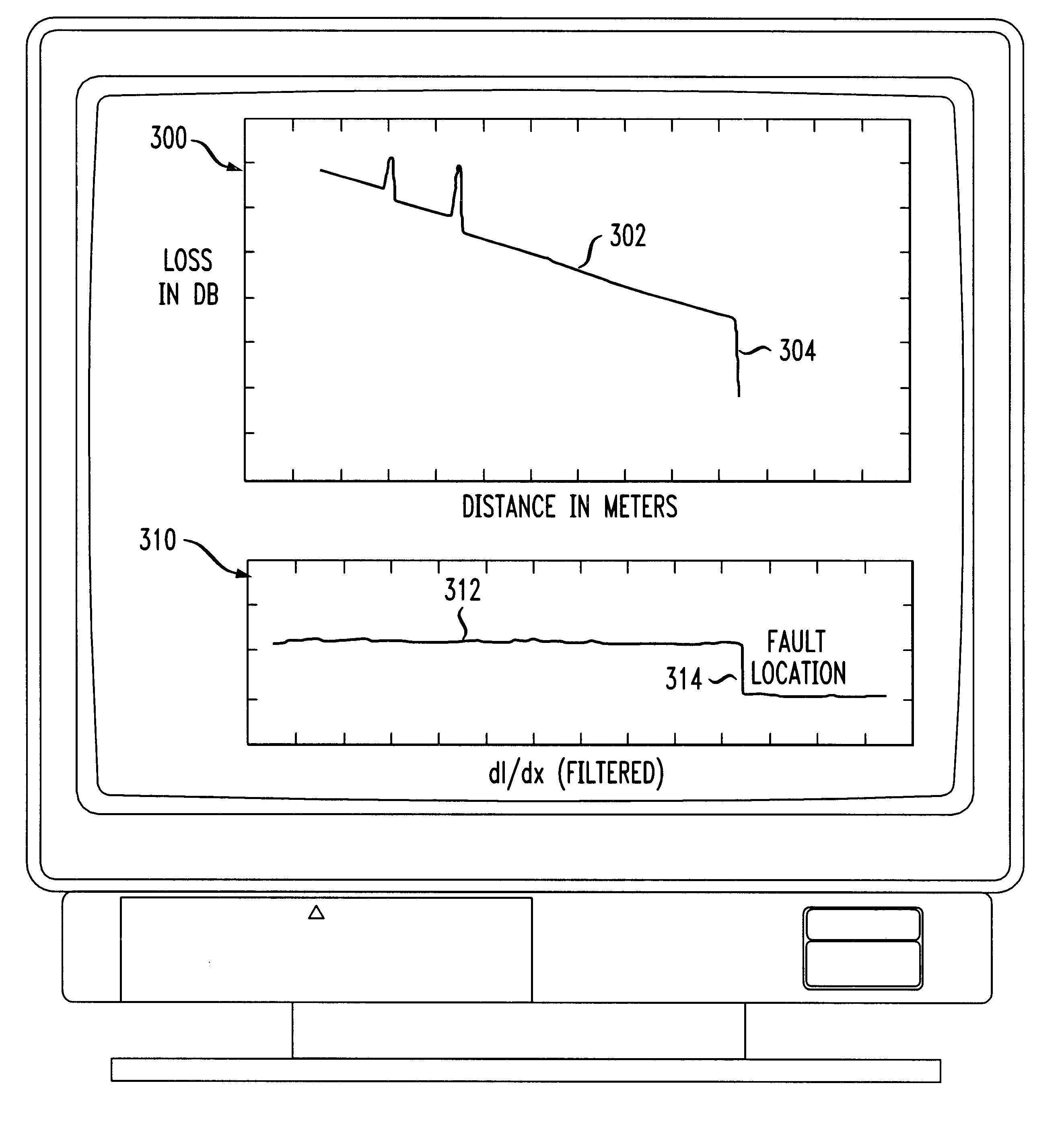
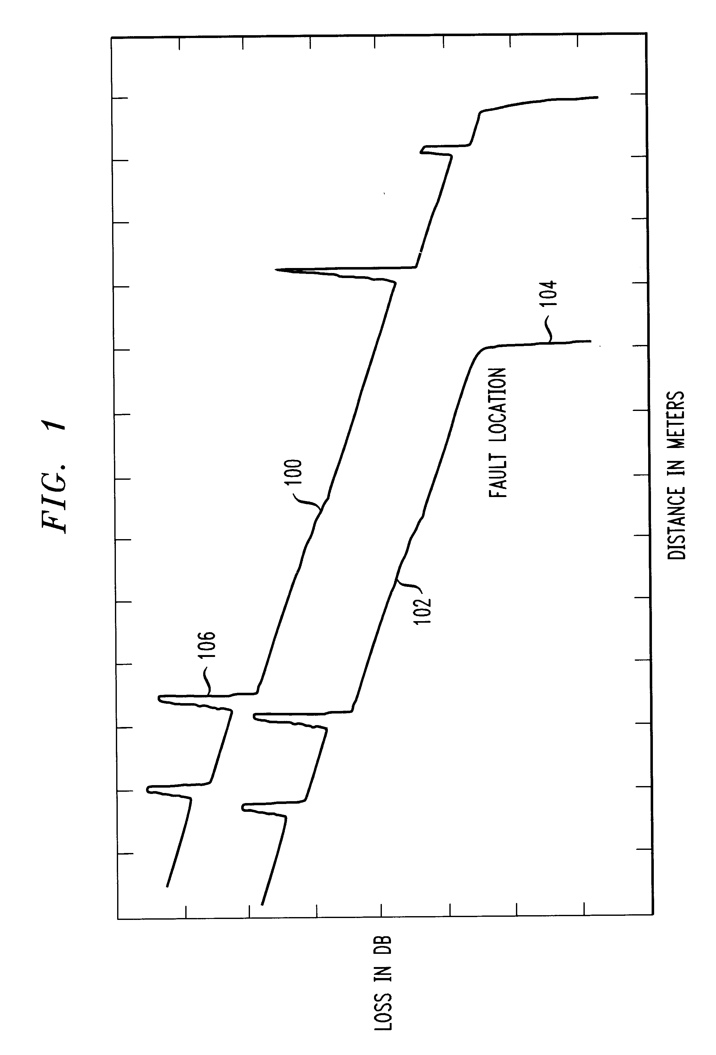
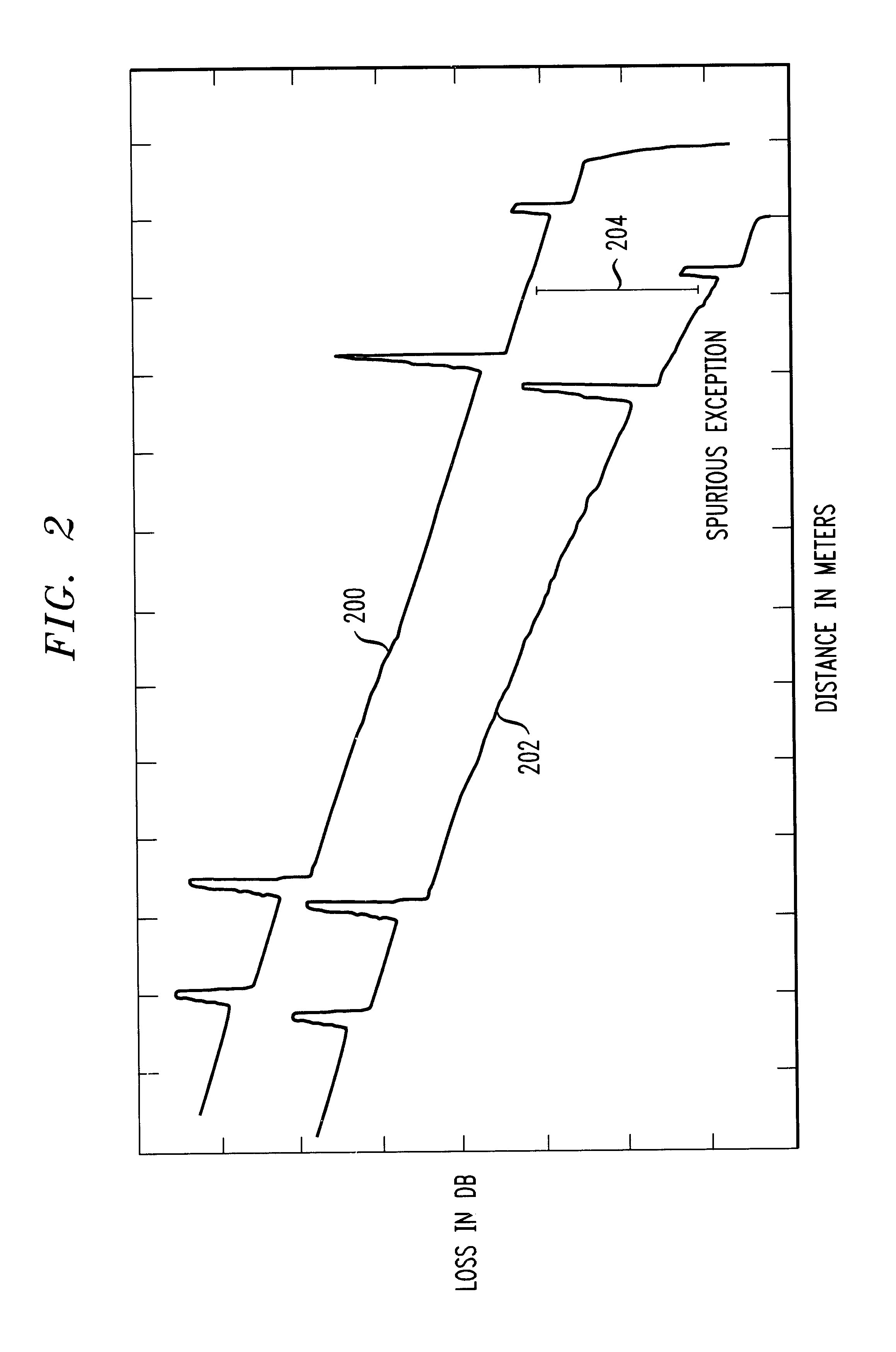
A method and apparatus for fault detection in a fiber-optic cable is presented. In one method of the present invention an OTDR is used for fault detection. A computer and a database are associated with the OTDR. The database includes reference trace information, on fiber-optic cables that are monitored by a specific OTDR The reference traces are stored for future use. Tests are made using information in the database and the test information (e.g. test trace) is stored in the database in response to the test made by the OTDR. The computer pr...


PUM


Abstract

The present invention is directed to a method and apparatus for testing a fiber-optic cable. An Optical Time Domain Reflectometer (OTDR) is presented. Test signals are generated from the OTDR and received by the OTDR for processing. The received test signals are sampled and analyzed. The received test signals include reflectance spikes and a slope. A first-order derivative is taken of the received signal. The first-order derivative is then filtered to remove the reflectance spikes and the slope. Discontinuities in the filtered first-order derivative denote a fault in the fiber-optic cable.

Description

1. Field of the InventionThis invention relates to testing. Specifically, the present invention relates to testing fiber-optic cables.2. Description of the Related ArtWith the expansion of the Internet, wireless communications and conventional telephony, the need for communication services has increased. The increased need for communication services correlates to an increased need for communication infrastructure. Modern high bandwidth communication infrastructure is typically implemented with fiber-optic cable.Fiber-optic cable provides high bandwidth communications. The cable itself typically consists of a glass-like core surrounded by several layers of protective material. Communication is accomplished in fiber-optic cable by transmitting light down the glass-like core. Information is modulated on the light and conveyed between transmission points. The light travels on material (e.g. core material) that serves as a transport medium. The transport medium has characteristic propert...

Claims


Application Information

Patent Timeline
IPC IPC(8): G01M11/00
CPCG01M11/3109
Inventor ASHER, MICHAEL L.ESLAMBOLCHI, HOSSEINGIDDENS, CHARLES C.GILES, CHRISTOPHER ROLLINHUFFMAN, JOHN SINCLAIRSTEWART, HAROLD JEFFREY
Owner AMERICAN TELEPHONE & TELEGRAPH CO
Why Eureka
Try Eureka