Resin and gas injection molding method with subsequent cohering

a gas injection molding and resin injection technology, applied in the field of resin injection molding methods, can solve the problems of non-uniform flow, transcription defects, mold defects, etc., and achieve the effect of high solubility

Inactive Publication Date: 2004-01-13
MUNEKATA TAKATUKI OSAKA JP
View PDF9 Cites 18 Cited by
  • Summary
  • Abstract
  • Description
  • Claims
  • Application Information

AI Technical Summary

Benefits of technology

It is an object of the invention to provide an injection molding method that does not cause cosmetic defects and insures an improved transcription and gloss level of products, a reduction of weld lines, and also a reduction of defects such as a flow marks of the resin and a gas marks caused in gas injection molding.
According to the invention, a process of injection molding is provided which improves the surface transcription, gloss level and cosmetic appearance of molded products. The resin is filled into the cavity of a die to form a space between a resin surface and a die surface as to the the visible side of the product(s) to hold down the progress of surface freezing of the melted resin. Into the space fluid is injected which softens the surface of injected resin (skin layer). Subsequently, pressure of the resin in the cavity is increased by adding a holding pressure in order to cohere the resin to the surface of the die. The resin is then cooled down in the cavity of the die until the resin solidifies.
Referring to the drawings in particular, the injection molding method according to the present invention comprises forcefully forming a space between the melted resin and the die surface in the visible side of molded products visible immediately after the resin is filled in. A fluid capable of softening the skin layer such as a carbon dioxide gas is injected, or the space is formed while the gas is being injected. With this process, the glass transition point of the skin layer is lowered by dissolving the fluid into the skin layer formed on a visible surface of the molded product while compressing the space portion. Then the skin layer is again pressed to the die surface and is solidified behind a holding pressure process. As described above, the transcription, gloss level, and cosmetic appearance of the molded products can be improved without affecting fluidity of a resin by forming the space immediately after the resin is filled in. Then a fluid is injected for softening the skin layer into this space, and again adding or applying a pressure to the skin layer for molding. Further, by injecting a fluid with continuous increased pressure or step by step increased pressure, no adverse effect is given to the skin layer immediately after the resin is filled in, even if the fluid is finally injected under a high pressure. Alternatively, the space can gradually be formed between the die surface and a skin layer immediately after a resin is filled in. The space may be formed either by partially and finely moving to the back a movable side die or a surface of the fixed side die opposite to the visible surface and at the same time injecting a fluid into the space, or by injecting a fluid after moving to the back is stopped and a space between the resin and die surface is formed.

Problems solved by technology

The results inlude such troubles as transcription defects of the molded product, non-uniformity in flow due to the progress in freezing of the resin, and molding defects arise such as when jetting may occur.
With this method, however, the transcription is improved, but sink mark and warpage easily occur due to non-uniformity in solidifying and shrinkage of the resin.
As such, it is difficult to control the molding process advantageously.
In addition, the molding cycle time becomes longer, which results in economical problems such as the higher cost of the molded product.
With this method, however, the transcription improved, but a specific facility is required, and also the molding cycle time becomes longer, which is economically disadvantageous.
This results in flow that is unstable, and sometimes the surface of the molded product may have a defect because of not-uniform flow of the resin and non-uniformity in the flow rate of the resin.
Further as a resin is filled in a pressurized cavity space, sometimes insufficient filling may occur in the molded product.
It is difficult to control over gas exhausting.

Method used


Image

  • Resin and gas injection molding method with subsequent cohering
  • Resin and gas injection molding method with subsequent cohering
  • Resin and gas injection molding method with subsequent cohering

Examples


example 2

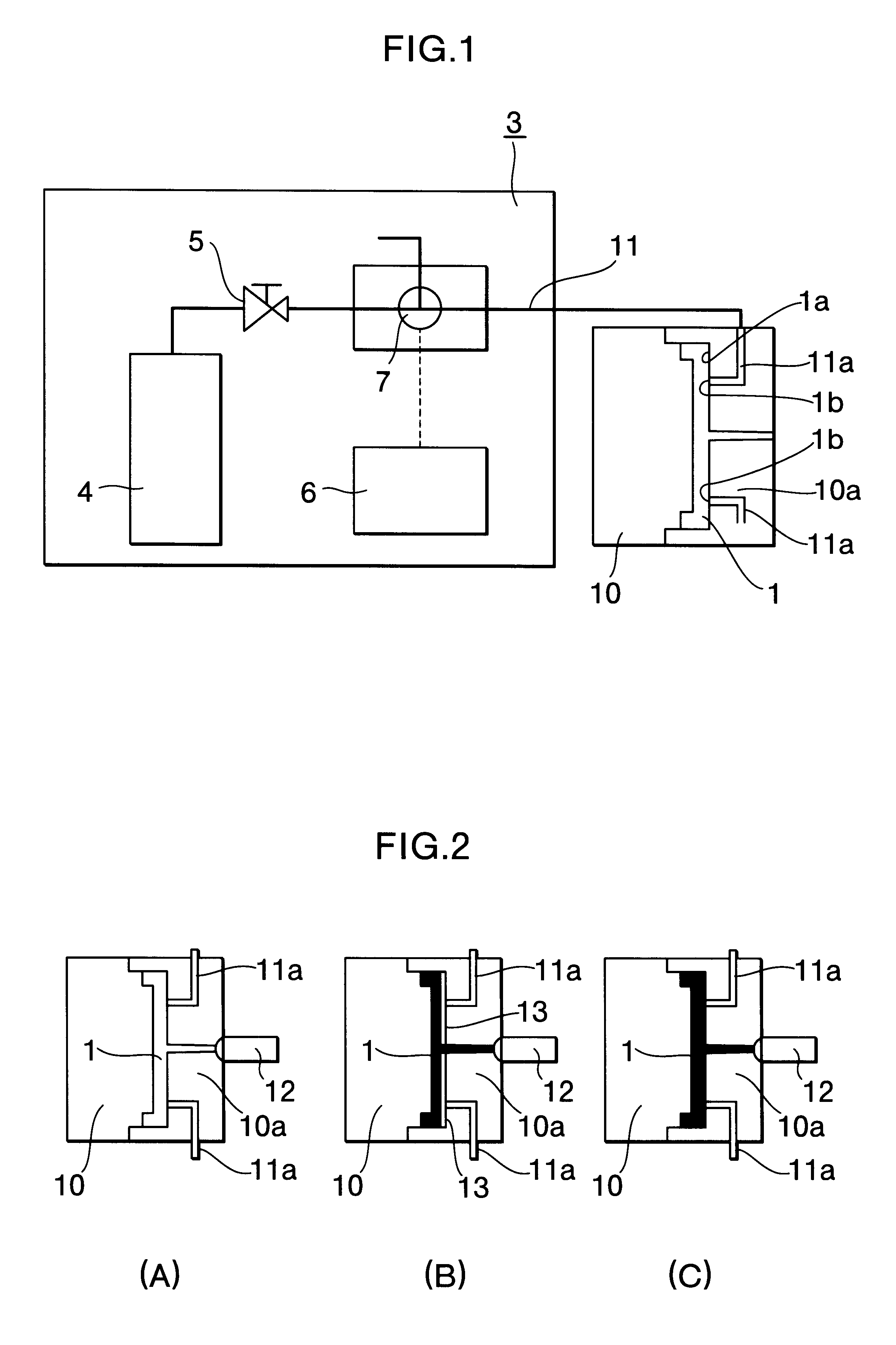
This example corresponds to another variant according to the invention. Molding as performed in the completely same way as that in Example 1 excluding the point that the carbon dioxide gas was continuously or intermittently injected into the space 13 formed. The total time consumed for injecting the gas was 2.0 sec, while exhaustion was executed for 0.2 sec, and in the case where gas injection was performed intermittently, the operation was divided to four stages, and an equal quantity of gas was injected in each stage. As a result, the molded product obtained as described above had excellent transcription, and had an excellent surface glossy level. The result of measurement of surface gloss level of the molded product is shown in Table 1.

Control 1

Molding was performed in the completely same way excluding the step relating to gas injection, which was not carried out. As a result, the molded product obtained as described had poor transcription qualities as compared to that in Example...

example 3

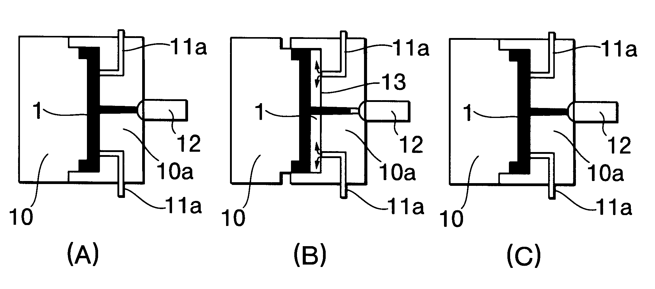
This example is yet another varient of the invention. Molding was performed in the completely same way excluding the point that, immediately after the melted resin was filled in, the surface of the fixed side die contacting visible side of the products was moved to the back to form the space 13 with the thickness of about 0.1 mm between the resin and the die surface, the carbon dioxide gas was injected into this space 13 like in Example 1, and then after the carbon dioxide gas was dissolved only in the resin surface (visible skin surface) of the visible side of the product, the die surface moved to the back was again moved forward, and then a further holding pressure was applied. The result of measurement of the gloss level of the molded product is shown in Table 1.

Control 2

Molding was performed in the completely same way as that in Example 2 excluding the step of injection of carbon dioxide gas, which was not carried out. As a result, it was confirmed that the molded product obtain...

example 4

Molding was performed in the completely same way as in Example 1 excluding the point that a gas injection inlet was provided at one place. It was confirmed that the molded product obtained as described above had excellent transcription qualities and an excellent surface gloss level of the molded product. The result of measurement of the surface gloss level of the molded product is shown in Table 1.

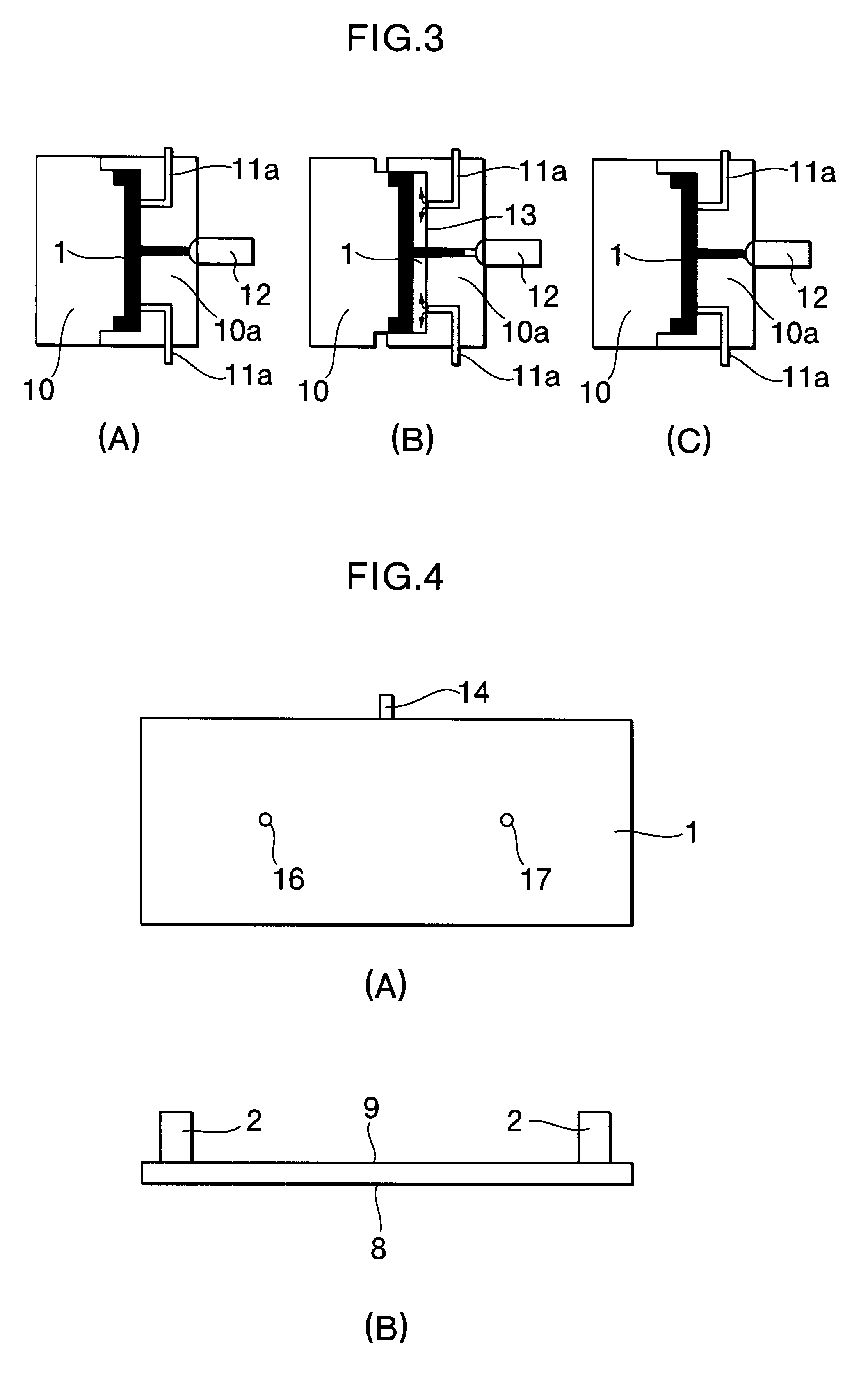
FIG. 4 and FIG. 5 shows the molded products obtained in the examples described above. In these figures, designated at the reference numeral 8 is a visible surface of the molded product, at 9 a not-visible surface thereof, at 14 a gate position in the molded product, at 15 a position of the inlet 1b when the gas is injected from one place, and at the reference numerals 16 and 17 positions of the inlets when gas is injected from two places.

With the invention as described in claims 1 to 6, immediately after a resin is filled in a die cavity, a space is formed between a surface of a die in the...


PUM

PropertyMeasurementUnit
sizeaaaaaaaaaa
temperatureaaaaaaaaaa

Abstract

The present invention provides an injection molding method for providing a molded product with excellent transcription and an excellent gloss level. In this method, immediately after a resin is filled in a cavity (1), a carbon dioxide gas is injected or the skin layer is moved back to form a space (13) between the resin and the die surface (1), so that growth of the skin layer is hold down, and at the same time the carbon dioxide is dissolved in the skin layer for lowering the glass transition point of skin layer. Then the skin layer is again closely cohered to a surface of the die by increasing the resin pressure and cooling the molded product for solidifying behind the holding pressure. With this method, products with excellent transcription and with an excellent surface gloss level can be obtained.

Description

The present invention relates to an injection molding method. More specifically, this invention relates to an injection molding method carried out by dissolving a carbon dioxide gas or a molding method for improving the transcription of products from a die surface or surfaces as well as improvinng a gloss level of the surface or surfaces of molded products.In injection molding of thermoplastics resin, generally, melted resin is filled in a cavity of a die, and the resin is cooled in the die to obtain molded products having the same form as the cavity. In this injection molding process, as a die is maintained at a lower temperature than the solidifying temperature of the resin. When the melted resin is filled in the cavity of die, freezing of the resin starts and proceeds immediately, and the so-called skin layer, which is a layer subjected to freezing, is formed on the surface of melted resin. Especially, a flow tip of the melted resin is transferred onto a surface of the molded pro...

Claims


Application Information

Patent Timeline
Patent Type & Authority Patents(United States)
IPC IPC(8): B29C45/00B29C45/17B29C43/02B29C45/56
CPCB29C43/021B29C45/0053B29C45/1701B29C2043/025B29C2043/3222B29C2043/527B29C2045/1702
Inventor TSUCHIYA, ATSUSHITATEYAMA, HIROFUMI
Owner MUNEKATA TAKATUKI OSAKA JP
Why Eureka
Try Eureka