Systems and methods for multi-resolution image defocusing

a multi-resolution, defocusing technology, applied in the field of defocusing a simulated image, can solve the problems of increasing the complexity of processing, the computational cost of a depth of focus calculation can be exceedingly high, and the contribution of each pixel can be combined using traditional computational costs,

Inactive Publication Date: 2004-01-13
MITUTOYO CORP
View PDF5 Cites 59 Cited by
  • Summary
  • Abstract
  • Description
  • Claims
  • Application Information

AI Technical Summary

Problems solved by technology

This occurs because the computational cost of a depth of focus calculation can be exceedingly high.
The traditional computational expense for combining the contributions of each pixel, using standard hardware, is proportional to the square of the radius of the circle of confusion.
In Potmesil's method, the complexity of the processing increases exponentially as the radius of the circle of confusion of each pixel increases.
Therefore, Potmesil's method can be extremely slow for significantly defocused images.
However, processing times for the first frame after the coherence is lost can still be significant.
Because focusing calculations take such a long time, defocus experimentation using computer generated images has been impractical.

Method used


Image

  • Systems and methods for multi-resolution image defocusing
  • Systems and methods for multi-resolution image defocusing
  • Systems and methods for multi-resolution image defocusing

Examples


Embodiment Construction

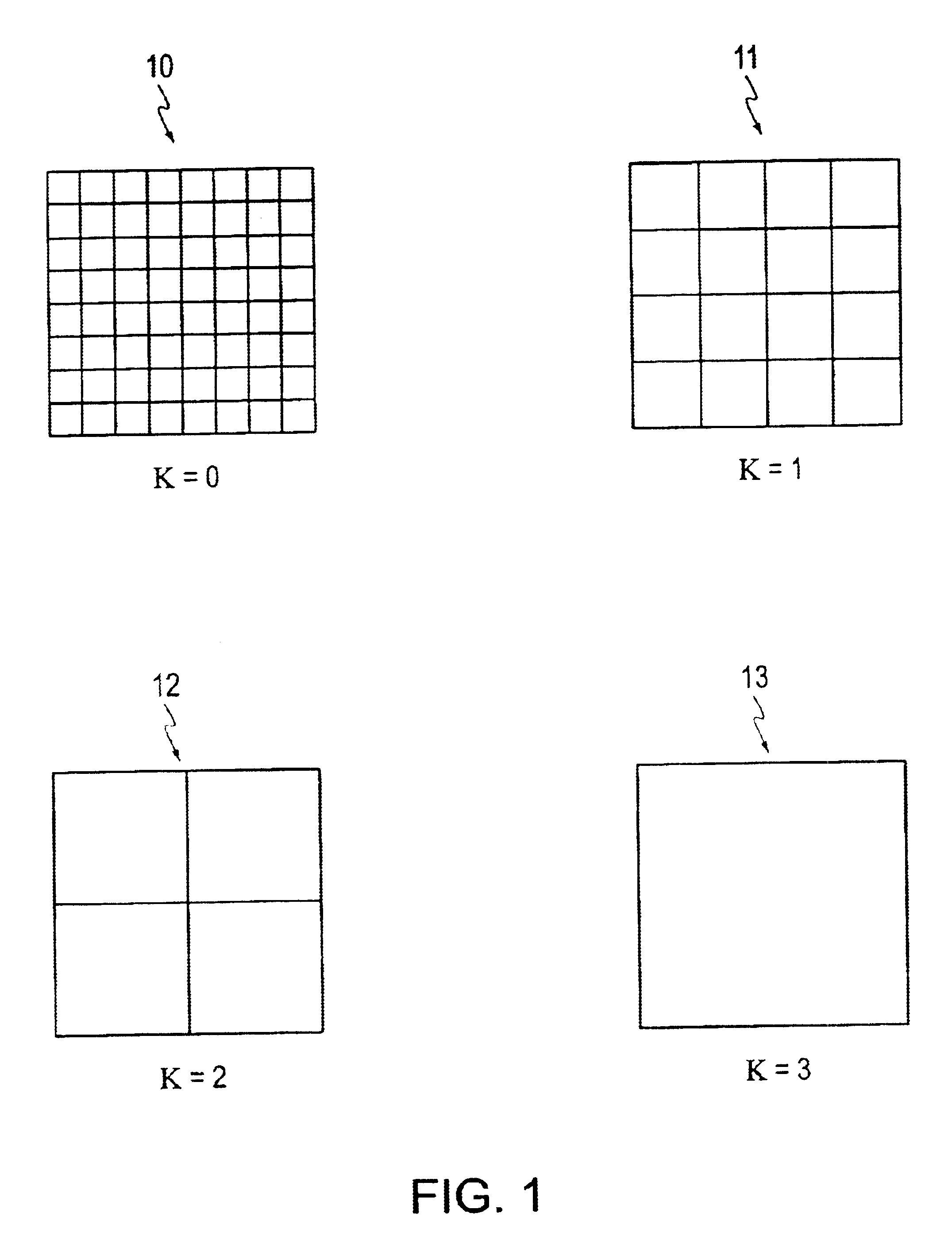
FIG. 1 shows four sets of image elements of the pyramid representation used by the defocused image generating systems and methods of this invention. These four sets of image elements result from a square image having a side length equal to 8 (=2.sup.3) pixels. In the first set 10 of picture elements, corresponding to the k=0 or zero-th level, each image element is a square having a side length equal to 2.degree., or 1, pixel. Thus, the first set 10 of image elements, i.e., the 0 level, has the same resolution as the original input image.

In the second set 11 of picture elements, or the k=1 or first level, each of the picture elements in the second set 11 is a square having a side length equal to 2.sup.1, or 2, pixels. In the third set 12 of image elements, or the k=2 or second level, each image element is a square having a side length equal to 2.sup.2, or 4, pixels. The fourth set 13 of image elements, or the k=3 or third level, has a single image element having a side length equal t...


PUM


Abstract

The defocused image generating methods and systems defocus an image using sets of image elements of a multi-resolution pyramid representation of the input image. Each pixel in the original image generates a region of confusion based on the image depth data for that pixel. The sets of image elements are used to represent the region of confusion using increasingly higher resolution image elements. The final defocused image is generated by compositing or combining together the sets of image elements after the region of confusion of each pixel has been decomposed into the sets of image elements.

Description

1. Field of InventionThis invention is directed to defocusing a simulated image. More particularly, this invention is directed to simulating defocusing in synthetic images using multiple resolutions.2. Description of Related ArtDepths of focus calculations are rarely performed in real-time graphics applications even though they can be quite valuable. This occurs because the computational cost of a depth of focus calculation can be exceedingly high. Conventionally, a single defocused frame can take several minutes to generate. To make matters worse, simple depth of focus control usually requires a long sequence of related frames."A Lens and Aperture Camera Model for Synthetic Image Generation", Potmesil et al, Computer Graphics, ACM Press (1981) describes a method for simulating depth of field effects caused by a lens and aperture in a computer graphics system. The method is a two-pass post-filtering process. The first pass computes an image and a corresponding z-depth map. The secon...

Claims


Application Information

Patent Timeline
Patent Type & Authority Patents(United States)
IPC IPC(8): G06T1/00G06F3/12G06T15/00
CPCG06T5/002
Inventor WASSERMAN, RICHARD M.YU, DAHAI
Owner MITUTOYO CORP
Why Eureka
Try Eureka