Vehicle air conditioner with flow area adjustment of fluid in heating heat exchanger

a technology of flow area adjustment and vehicle air conditioner, which is applied in the direction of indirect heat exchangers, ducting arrangements, lighting and heating apparatus, etc., can solve the problems of increased production cost of hot water valves, difficulty in continuously adjusting the temperature of air blown into passenger compartments, and inability to quickly respond to a change in the flow amount or the temperature of hot water

Inactive Publication Date: 2004-01-20
DENSO CORP
View PDF10 Cites 11 Cited by
  • Summary
  • Abstract
  • Description
  • Claims
  • Application Information

AI Technical Summary

Benefits of technology

Preferably, the heating heat exchanger has a plurality of tubes through which the fluid flows to heat air. Further, the flow control member is disposed to change a ratio between a first number of the tubes in which the fluid flows, and a second number of the tubes in which the fluid does not flow. Accordingly, the flow ratio of the hot air amount and the cool air amount can be readily changed using the flow control member.
Preferably, the heating heat exchanger includes a core portion having the tubes, and a tank member for distributing the fluid into and for collecting the fluid from the tubes, and the flow control member is disposed in the tank member to be movable in the tank member so that an inner space of the tank member is partitioned in a tube arrangement direction where the tubes are arranged. Further, the flow control member is moved linearly in the tube arrangement direction to change the ratio between the first number of the tubes in which the fluid flows, and the second number of the tubes in which the fluid does not flow. Therefore, the flow control member can be readily disposed in the tank member of the heating heat exchanger while having the air mixing function.
Preferably, a pressure-loss increasing portion is provided in the air conditioning case to increase an air pressure loss around a one tube among all the tubes, in which the fluid firstly flows. Therefore, it can prevent the temperature of air blown into the passenger compartment from being rapidly increased when an opening degree of the flow control member, for opening the tubes, is set at a very small degree from zero. Accordingly, temperature control performance of the vehicle air conditioner can be effectively improved. Alternatively, among all the tubes, one tube into which the fluid firstly flows is disposed at an outermost side in the core portion. Even in this case, the same advantages can be obtained.
Preferably, a plurality of ribs are disposed at a downstream air side of the heating heat exchanger in the air conditioning case, for disturbing an air flow from the heating heat exchanger. Therefore, air mixing performance can be improved, and a temperature difference in air blown into the passenger compartment can be reduced. Alternatively, a guide member is disposed at a downstream air side of the heating heat exchanger in the air conditioning case, for guiding one of air from the first area and air from the second area to a side of the other one. Even in this case, the air mixing performance can be improved.

Problems solved by technology

However, since the heat capacity of the heating heat exchanger is large, the air temperature cannot fast respond to a change of the flowing amount or the temperature of hot water flowing into the heating heat exchanger.
Therefore, it is difficult to continuously adjust the temperature of air blown into the passenger compartment from a low temperature range to a high temperature range.
However, in this case, production cost of the hot water valve is increased.

Method used


Image

  • Vehicle air conditioner with flow area adjustment of fluid in heating heat exchanger
  • Vehicle air conditioner with flow area adjustment of fluid in heating heat exchanger
  • Vehicle air conditioner with flow area adjustment of fluid in heating heat exchanger

Examples


second embodiment

(Second Embodiment)

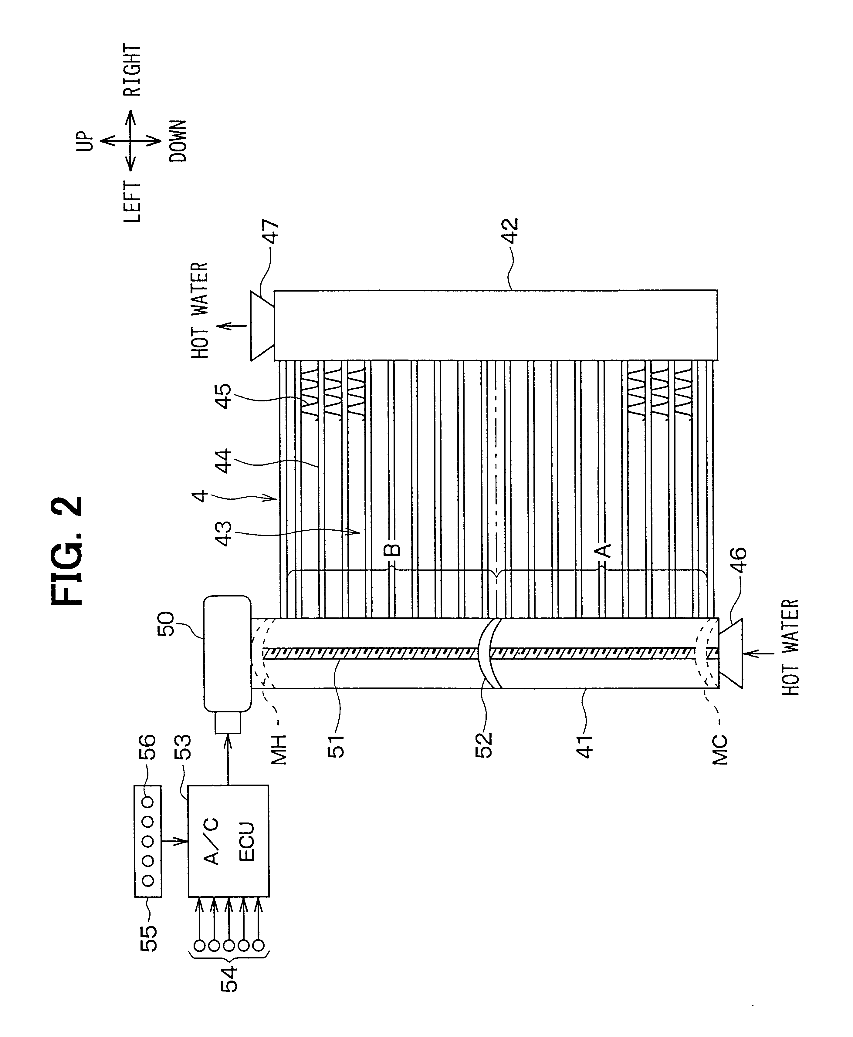
In the above-described first embodiment, the heater core 4 is disposed to cross the entire section area of the air passage in the air conditioning case 1a so that all air from the evaporator 3 passes through the heater core 4. However, in the second embodiment, as shown in FIG. 4, the height of the heater core 4 is made smaller than that of the evaporator 3, and a cool-air bypass passage 60 is provided above the heater core 4 in the air conditioning case 1a. The cool-air bypass passage 60 is opened and closed by a bypass door 61, and the bypass door 61 is driven by an actuator (not shown) controlled by the air-conditioning electronic control unit 53. When the cool-air bypass passage 60 is opened by the bypass door 61, cool air having passed through the evaporator 3 can be directly introduced to at least one of the defroster opening 5 and the face opening 6 through the cool-air bypass passage 60.

In an air outlet mode such as a foot / defroster mode where the defroste...

third embodiment

(Third Embodiment)

In the above-described first and second embodiments, the flow control member 52 is movably disposed only in the inlet tank 41 of the heater core 4. However, in the third embodiment, as shown in FIG. 5, two flow control members 52a, 52b are movably disposed in the inlet tank 41 and the outlet tank 42 of the heater core 4, respectively. Therefore, two actuators 50a, 50b and two screw rotation shafts 51a, 51b are disposed for the flow control members 52a, 52b, respectively.

Accordingly, in the third embodiment, the flow control members 52a, 52b can be independently moved to desired positions by the actuators 50a, 50b, respectively. Therefore, the flow amount ratio between the hot air and the cool air, that is, the number ratio between the water-flowing flat tubes 44 where hot water flows and the non-water-flowing flat tubes 44 where no hot water flows can be adjusted as in the first embodiment. In addition to this function, the positions of the water-flowing flat tubes...

fourth embodiment

(Fourth Embodiment)

In the above-described first to third embodiments, hot water flows in one way from the inlet tank 41 to the outlet tank 42. However, in the fourth embodiment, hot water flows in the heater core 4 while being turned in a U-shape in an air flow direction D, as shown in FIGS. 6A-6C. Specifically, the inlet tank 41 and the outlet tank 42 are disposed at one end side of the heater core 4 in the vehicle right-left direction, to be arranged adjacent to each other in the air flow direction D. As shown in FIGS. 6B, 6C, the outlet tank 42 is disposed at an upstream side of the inlet tank 41 in the air flow direction D, thereby improving heat-exchange efficiency between air and hot water. Here, the flat tubes 44 are composed of plural first tubes 44a disposed at a downstream air side to communicate with the inlet tank 41, and plural second tubes 44b disposed at an upstream air side of the first tubes to communicate with the outlet tank 42.

In the heater core 4, a connection t...


PUM


Abstract

In a vehicle air conditioner, a flow control member is disposed in an inlet tank of a heating heat exchanger for heating air to be blown into a passenger compartment using a fluid as a heating source. In the heating heat exchanger, a ratio between a first area where the fluid flows, and a second area where the fluid does not flow is changed by controlling an operation position of the flow control member. Thus, a flow ratio between hot air from the first area of the heating heat exchanger and cool air from the second area thereof can be adjusted, so that the temperature of air blown into the passenger compartment can be adjusted.

Description

This application is related to and claims priority from Japanese Patent Applications No. 2001-277055 filed on Sep. 12, 2001, No. 2002-174149 filed on Jun. 14, 2002, and No. 2002-203985 filed on Jul. 12, 2002, the contents of which are hereby incorporated by reference.1. Field of the InventionThe present invention relates to a vehicle air conditioner for adjusting an air temperature blown into a passenger compartment by changing a ratio of a fluid flowing area to a non-fluid flowing area in a heating heat exchanger. Here, a fluid such as hot water, used as a heating source, flows in the fluid flowing area in the heating heat exchanger, and no fluid flows in the non-fluid flowing area in the heating heat exchanger.2. Description of Related ArtConventionally, an air mixing system and a hot-water adjusting system are known as an air-temperature adjusting system of a vehicle air conditioner. In the air mixing system, an air temperature to be blown into a passenger compartment is adjusted...

Claims


Application Information

Patent Timeline
Patent Type & Authority Patents(United States)
IPC IPC(8): B60H1/00F28F9/02F28F27/00F28F27/02B60H1/08F24F13/02F28F9/22F28F13/06F28F13/12
CPCB60H1/00028B60H1/00328F28F9/0212F28F27/02B60H2001/00157B60H2001/00171F28D2021/0096F28F2250/06
Inventor OKUMURA, YOSHIHIKONISHIKAWA, KATSUMIAKATSUKA, TOMONORI
Owner DENSO CORP
Why Eureka
Try Eureka