Control device for direct-injection spark-ignition engine and method of setting fuel injection timing of the same

a technology of direct injection and spark ignition, which is applied in the direction of electric control, ignition automatic control, machines/engines, etc., can solve the problems of fuel dispersion in higher engine speed ranges, difficult to maintain a good stratified charge combustion state over wide engine speed ranges, etc., and achieve the effect of improving the fuel economy of direct injection spark ignition engines

Inactive Publication Date: 2004-01-27
MAZDA MOTOR CORP
View PDF5 Cites 33 Cited by
  • Summary
  • Abstract
  • Description
  • Claims
  • Application Information

AI Technical Summary

Benefits of technology

to provide a control device and a method of setting fuel injection timing for a direct-injection spark-ignition engine in which a stratified combustible mixture is produced using a tumble. It is a more specific object of the invention to provide a control device and a fuel injection timing setting method which make it possible to improve fuel economy of a direct-injection spark-ignition engine by causing the engine to make stratified charge combustion in a preferable fashion in stratified charge combustion regions over wide engine speed ranges from low-speed to high-speed ranges.

Problems solved by technology

A conventional direct-injection spark-ignition engine using the tumble like the one shown in Japanese Unexamined Patent Publication No. 2000-104550 has a problem that it is difficult to maintain a good stratified charge combustion state over wide engine speed ranges from low-speed to high-speed ranges.
Even if the fuel spray penetration is balanced with the intensity of the tumble flow in accordance with the increase in the engine speed in this fashion, however, there arises another problem that the fuel tends to be dispersed in higher engine speed ranges as a result of an increase in hydraulic impact energy.

Method used


Image

  • Control device for direct-injection spark-ignition engine and method of setting fuel injection timing of the same
  • Control device for direct-injection spark-ignition engine and method of setting fuel injection timing of the same
  • Control device for direct-injection spark-ignition engine and method of setting fuel injection timing of the same

Examples


Embodiment Construction

The invention is now described, by way of example, with reference to the accompanying drawings.

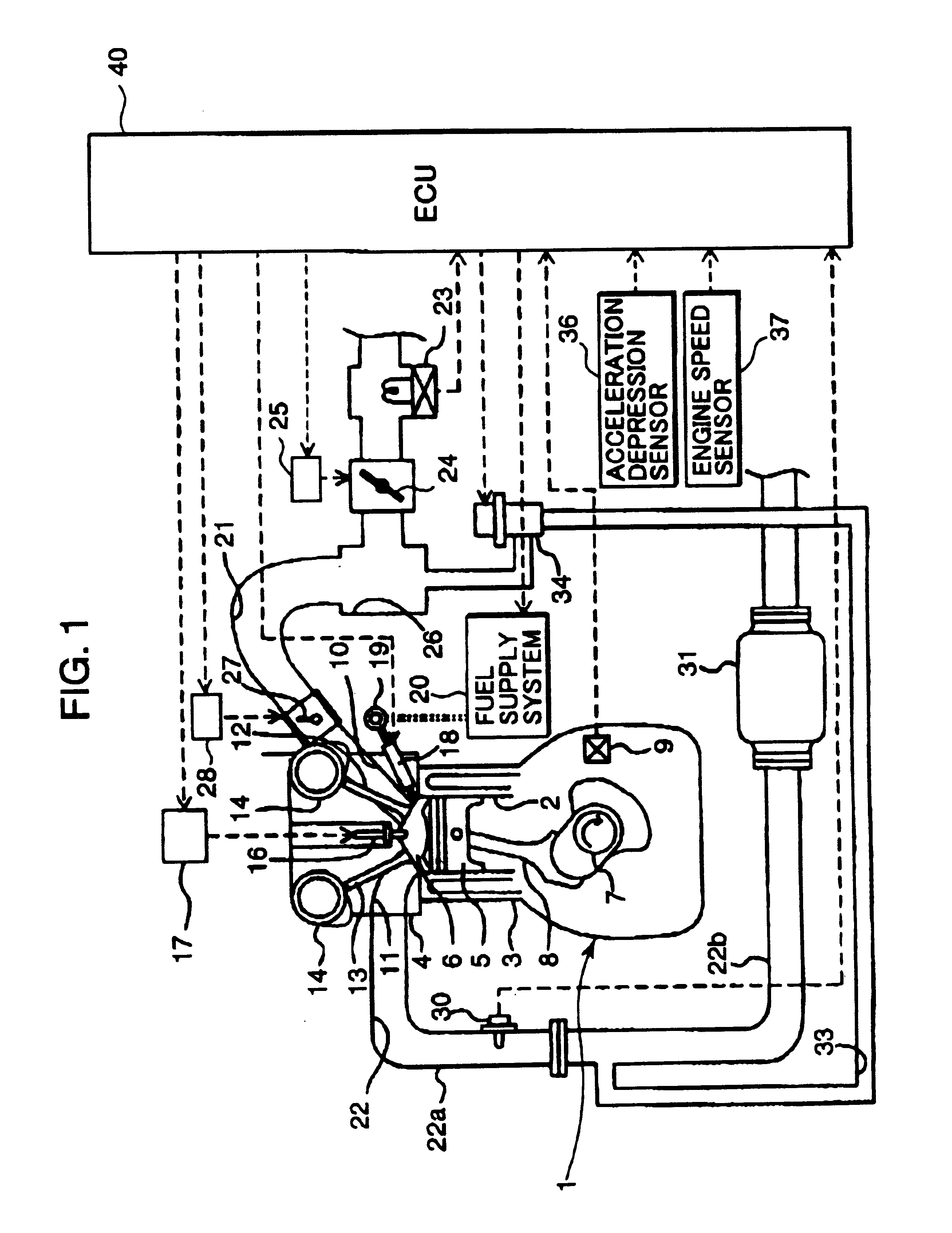
FIG. 1 is a diagram showing the overall construction of an example of a direct-injection spark-ignition engine employing a control device according to a preferred embodiment of the invention. Referring to the Figure, an engine body 1 has a cylinder block 3, in which a plurality of cylinders 2 are formed, and a cylinder head 4. Pistons 5 are fitted in the individual cylinders 2 in such a manner that the pistons 5 can move up and down, and a combustion chamber 6 is formed between each piston 5 and the cylinder head 4. Each piston 5 is linked to a crankshaft 7 by a connecting rod 8, the crankshaft 7 being rotatably supported at a lower part of the cylinder block 3. There is provided a crank angle sensor 9 for detecting the angle of rotation of the crankshaft 7, or the crank angle, at one end of the crankshaft 7.

The combustion chamber 6 in each cylinder 2 has a pent-roof shaped ceiling formed ...


PUM


Abstract

A direct-injection spark-ignition engine in which a combustible mixture is produced around a spark plug at an ignition point by causing a tumble and a fuel spray to collide with each other in a combustion chamber during stratified charge combustion comprises a fuel pressure controller which controls fuel pressure such that penetration of the fuel spray from a fuel injector is progressively intensified with an increase in engine speed in a stratified charge combustion region and means for controlling fuel injection timing including an injection timing setter. The means for controlling fuel injection timing controls the injection timing in such a way that the interval between a fuel injection ending point and the ignition point becomes progressively shorter as engine speed increases under the same engine load conditions in the stratified charge combustion region.

Description

BACKGROUND OF THE INVENTION AND RELATED ART STATEMENTThe present invention relates generally to a direct-injection spark-ignition engine having an injector for injecting fuel directly into a combustion chamber, in which a stratified combustible mixture is produced around a spark plug using a tumble during operation by stratified charge combustion. More particularly, the invention pertains to a control device for controlling fuel injection and other factors of such a direct-injection spark-ignition engine as well as to a method of setting fuel injection timing of the same.In one example of a conventionally known direct-injection spark-ignition engine provided with an injector for injecting fuel directly into a combustion chamber, the air-fuel ratio is increased to produce a lean mixture and the injector injects the fuel during every compression stroke such that the mixture is locally distributed around a spark plug to cause stratified charge combustion in a low-speed low-load operati...

Claims


Application Information

Patent Timeline
Patent Type & Authority Patents(United States)
IPC IPC(8): F02D37/02F02D41/14F02D37/00F02D41/40F02D41/30F02B75/00F02B31/00F02B75/12F02B17/00F02F3/26F02P5/15F02B23/08F02B23/10F02D41/02F02D41/04F02D41/34F02D43/00F02D45/00F02M25/07
CPCF02D37/02F02D41/3029F02D41/34F02D41/401F02B17/005F02B31/00F02B2075/125F02D2041/389F02D2200/1015F02F3/26Y02T10/44Y02T10/123Y02T10/12Y02T10/40F02D41/40
Inventor MAMIYA, KIYOTAKATETSUNO, MASAYUKIYAMAUCHI, TAKEOOHTA, NORIYUKI
Owner MAZDA MOTOR CORP
Why Eureka
Try Eureka