Apparatus for removal of ice from a storage bin

a technology for removing ice and storage bins, applied in the field of ice storage bins, can solve the problems of inability to meet the needs of ice dispensing equipment, lack of versatility of prior art ice dispensing equipment, and manual bridge breaking intervention, so as to prevent ice bridging

Inactive Publication Date: 2004-02-03
FOLLETT PROD LLC
View PDF20 Cites 31 Cited by
  • Summary
  • Abstract
  • Description
  • Claims
  • Application Information

AI Technical Summary

Benefits of technology

Additionally, there is an upper bin section that has tapered walls to prevent bridging of ice therein, which facilitates the gravity dropping of ice from the upper bin to the lower bin. The lower bin section is separate from its structural support or frame, the latter carrying the drive loads, which frees the lower bin from carrying the drive loads.
It is another object of this invention to provide an upper bin section that has tapered walls, to prevent bridging of ice therein.

Problems solved by technology

One disadvantage of such prior art type of devices is that they lack durability and require manual bridge-breaking intervention in order to keep the ice loose so the ice will properly dispense.
Such manual agitation can create adverse sanitation problems.
Additionally, prior art ice dispensing equipment is often lacking in versatility.

Method used


Image

  • Apparatus for removal of ice from a storage bin
  • Apparatus for removal of ice from a storage bin
  • Apparatus for removal of ice from a storage bin

Examples


Embodiment Construction

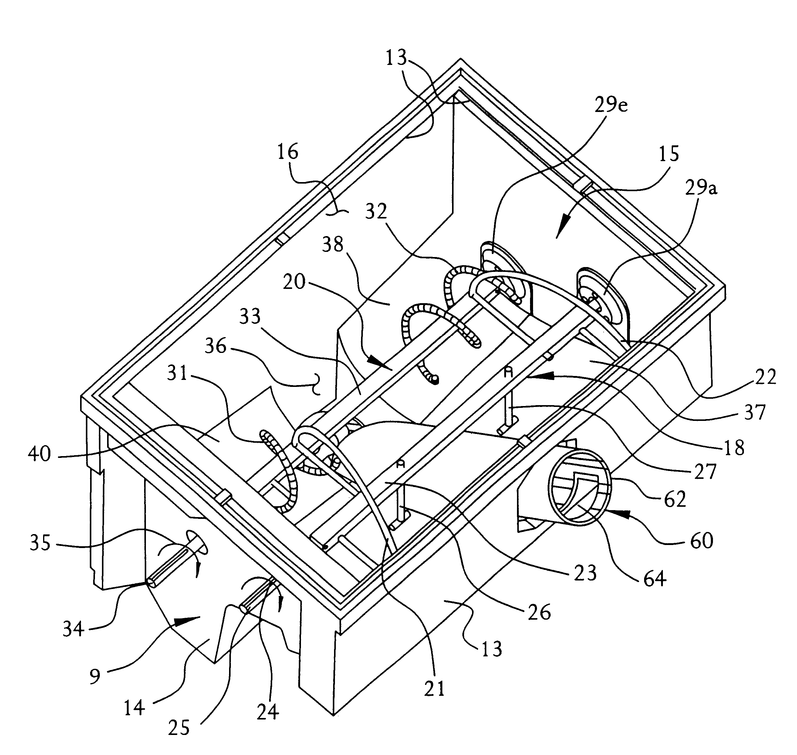
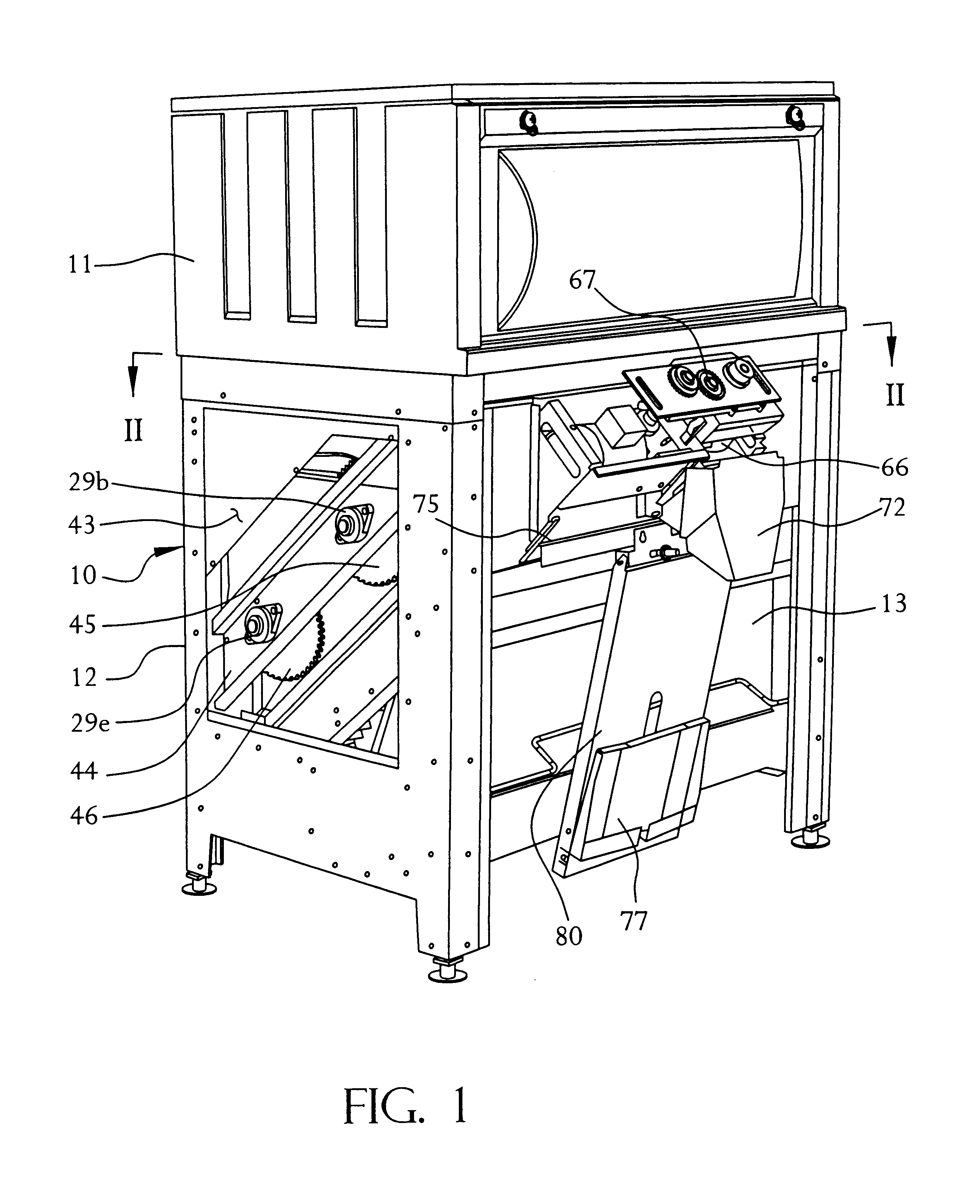
Referring now to the drawings in detail, reference is first made to FIG. 1, wherein there is shown the apparatus 10 of this invention, including an upper ice bin 11 and a lower ice bin apparatus 12.

The ice making apparatus (not shown) may be of any conventional type, in that the particular ice making apparatus does not form an essential part of the present invention. Generally, the ice making apparatus will, however, be a suitable type of apparatus for making ice in the form of ice cubes, pieces, particles, shavings, or nuggets, and will generally be disposed above the upper bin 11, although, in the alternative, the same could be disposed at a location remote from the ice bin 11, with a suitable delivery system for delivering ice into the ice storage area provided by the bin 11. However, preferably, the ice making apparatus will be disposed generally above the bin 11, such that ice may pass to the ice bin 11, via gravity, and then enter the bin 12, via gravity.

With reference to FIG....


PUM


Abstract

An apparatus for storing ice in a container and dispensing ice from the container is provided in the form of a storage bin, having ice agitating apparatus for engaging ice to loosen the same and to keep ice particles from adhering together in a common mass. An ice dispenser is provided for delivering ice from a lower to an upper end. The ice dispenser and the ice agitator are provided with separate drives.

Description

Ice dispenser bins are used in many situations, wherein ice is periodically made or generated and delivered or dropped into a storage bin, where it resides until the need arises to use the ice. In order to keep the ice pieces or particles from all adhering together into one large structure, it is known to agitate the ice. Generally, the ice pieces are dispensed from a lower location in the bin, to an upper location, to be discharged to bags, a cart, or other suitable container.Because ice is delivered from an upper location to a lower location, to be later moved from a lower location to an upper location, it is known that there sometimes forms a bridge of ice pieces, inhibiting the delivery of ice from the upper location to the lower location.It has become commonplace to periodically break up the bridge by reaching into the bin, manually, with a paddle, to strike the ice bridge and release the pieces or articles, to fall to the bottom of the bin.In some cases, there is provided a dr...

Claims


Application Information

Patent Timeline
Patent Type & Authority Patents(United States)
IPC IPC(8): G07F11/66G07F11/00G07F9/10
CPCG07F11/66G07F17/0071
Inventor HAWKES, RICHARD BLAIRHAUPT, BRIAN WAYNE
Owner FOLLETT PROD LLC
Why Eureka
Try Eureka