Polarization imaging system

a polarization imaging and imaging system technology, applied in the field of polarization imaging systems, can solve the problems of limited system practice, slow approach, and unreliable application of real-world samples

Inactive Publication Date: 2004-02-17
CAMBRIDGE RES & INSTR
View PDF6 Cites 56 Cited by
  • Summary
  • Abstract
  • Description
  • Claims
  • Application Information

AI Technical Summary

Problems solved by technology

But observations of this type alone do not reveal which is the fast axis and which the slow axis.
But the requirement for a spectrometer to analyze the content of light passing through the sample means that system is limited in practice to measuring a single point in the sample at a time.
In practice, this approach is slow because of the need for the calculation step, and has proven unreliable when applied to real-world samples.
But the system is inherently point-wise in nature, and cannot be readily extended to produce an image of retardance at every point in an object, except by taking a grid of point-wise measurements.
This is impractical when one seeks images having even moderate spatial definition.
While it is said to provide complete information about the sample retardance, this arrangement is complex and has many moving parts.
Further, it measures only a point at a time, so is ill-suited to providing a high-definition image of birefringence or retardance across an entire sample.
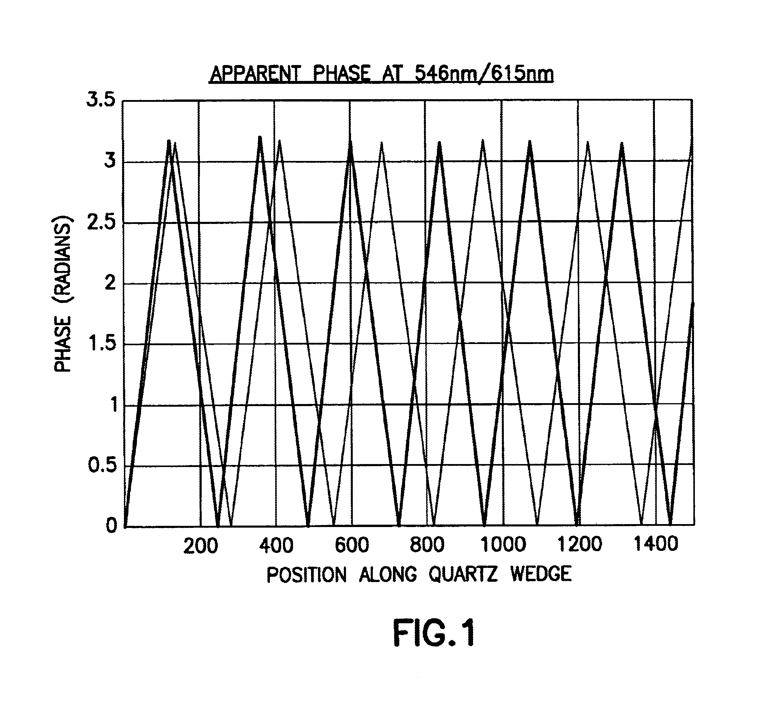
Contrary to the teaching, however, this method does not provide an unambiguous determination of R, since there are in fact many cases where two different values of R yield the same set of readings {R.sub.0 (.lambda..sub.1), R.sub.0 (.lambda..sub.2)}.
Thus, Sakai et. al. does not actually provide for unambiguously determining retardance.
However, this system suffers from the same ambiguities as the Sakai et. al. system, which are either not recognized or not acknowledged by the inventors. FIG. 6 of this patent clearly illustrates the shortcomings of the syst
lent. This is the same defect mentioned in connection with Sakai et. al. and it is equally limiti
This suffers the same problems as the Croizer approach described above, since it requires computation, and there must be significant spatial oversampling and / or certain assumptions must be made about the structure being imaged.
This suffers from the same limitations as the other system of Mason, namely the need for a spectrometer which makes it inherently a point sensing system that cannot readily be used to produce a two-dimensional image of a sample.
In summary, while there is extensive art for obtaining and interpreting isochrome and isocline images, none are satisfactory for providing identification of the fast and slow axis together with unambiguous determination of R in excess of .lambda. / 2 across a complete image.
All methods that seek to provide such information suffer from one or more of the following limitations: need for spatial analysis of the image to resolve order; reliance on stress-integral analysis to resolve order and provide axis determination; need for a priori knowledge about the distribution of stress and / or birefringence in the sample; possibility for confusion of certain values of retardance with other, widely-different values of retardance; need for observations at three wavelengths or across a continuous spectrum; inherent limitations that in theory permit measuring at most a line at a time, and in practice, a single point at a time.

Method used


Image

  • Polarization imaging system
  • Polarization imaging system
  • Polarization imaging system

Examples


Embodiment Construction

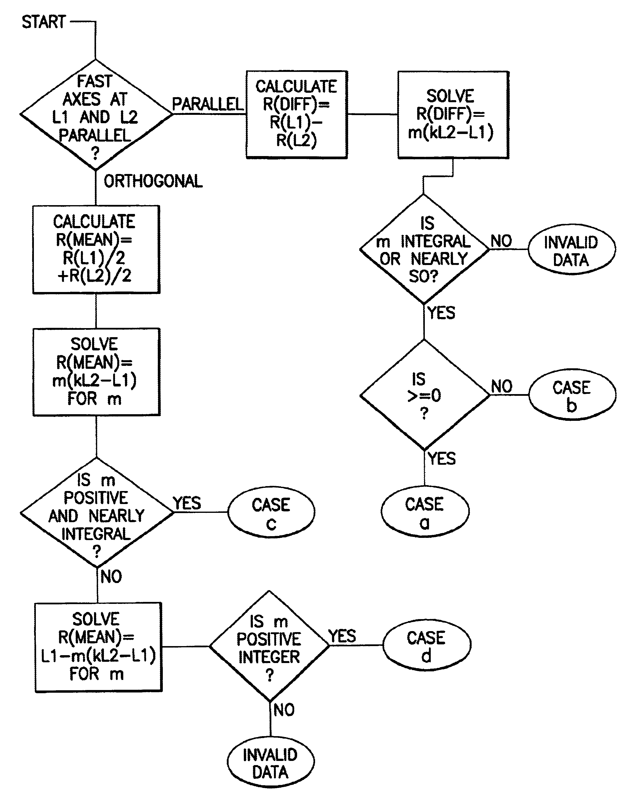
Throughout this description, certain embodiments will be described in terms of apparent phase, and others in terms of apparent retardance. This is done to illustrate that either approach is possible, and that indeed the two are equivalent. Similarly, while certain hardware is described being suitable for purposes of acquiring the images of apparent phase and fast axis orientation, any hardware may be used to acquire this information without deviating from the spirit of the present invention.

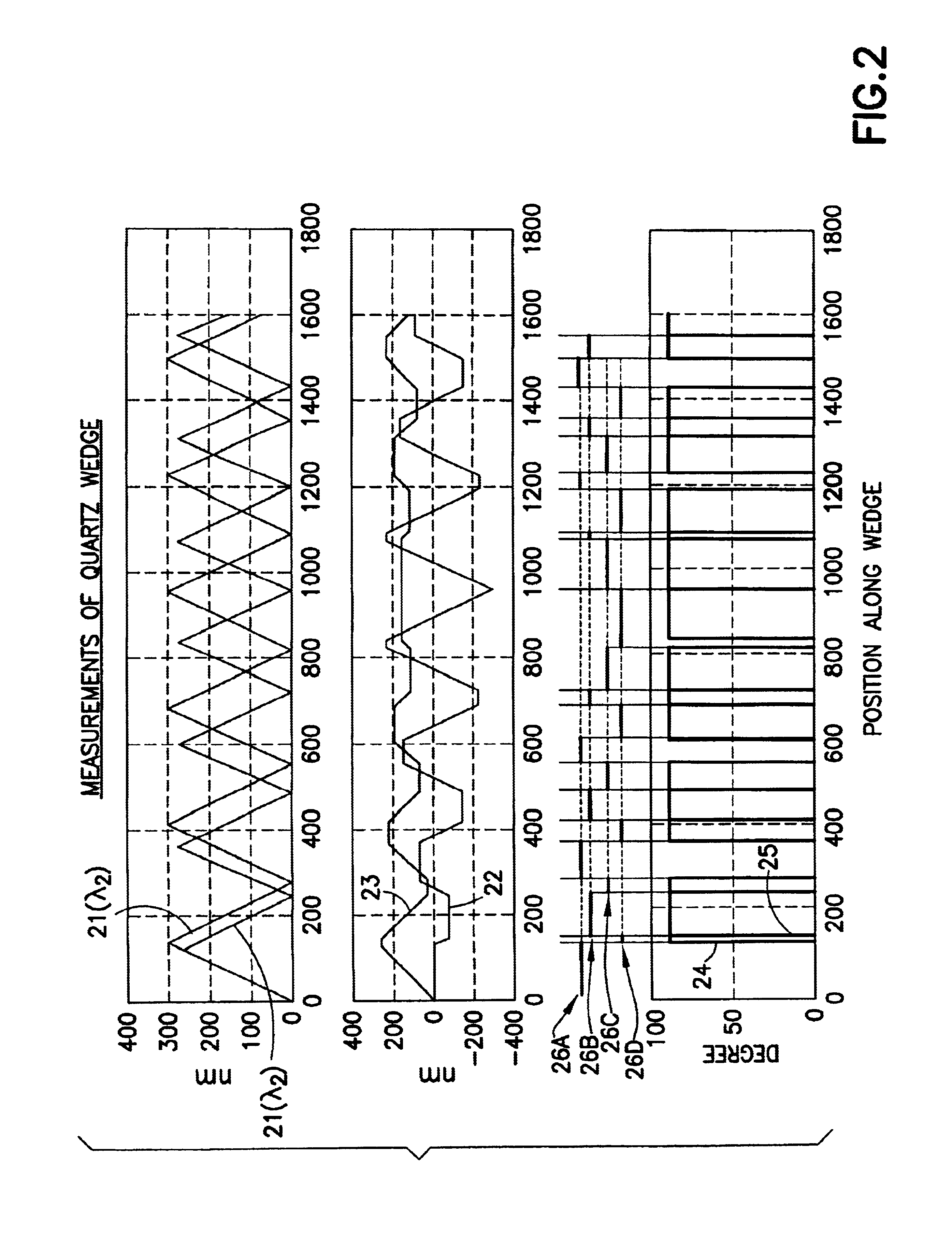
The preferred embodiment uses an optical system such as that described in Oldenbourg to obtain the images of apparent retardance and fast axis orientation at every point in the sample. These are made at two wavelengths .lambda..sub.1 and .lambda..sub.2 which are chosen so that the difference between them meets the condition

m.sub.max =.lambda..sub.1 / [.lambda..sub.2 -.lambda..sub.1 ] [6]

where m.sub.max is the highest order, m, that needs to be resolved by the system. For example, in a first prefer...


PUM


Abstract

A polarization imaging system and method are disclosed for measuring the magnitude and orientation of retardance in a sample. There are no moving parts and the invention is readily constructed as an imaging system that obtains polarization values at all point in a scene simultaneously. The system first takes an image that records the apparent slow axis orientation and the apparent retardance. However, the apparent retardance is indeterminate by mlambda, the wavelength of observation. By recording such images at two wavelengths, and taking note of both the apparent phase and the angular orientation of polarization interference in each of the two cases, the system is able to determine retardance values of 5lambda or more at every point without ambiguity. The actual slow axis orientation is determined as well. The determination of retardance value and axis orientation is independent for each point measured, and does not make use of spatial relationships or distributions within the sample.

Description

1. Field of the InventionThe invention is directed toward systems for measuring materials properties such as strain, crystallinity, thickness, purity, composition, and the like of samples; or for observing structures in transparent materials; or, for measurement of strain in models constructed for that purpose. It is more narrowly directed toward measuring systems that utilize polarized light for such measurements. It may be used in applications including scientific research, industrial measurement, quality control, forensics, and medical imaging.2. Description of the Related ArtPolarization interference is a well-known way to observe birefringence or retardance in a sample. Birefringence is an intensive property of a sample whereby light polarized along different axes will experience different indices of refraction. The axis along which the index is lowest is termed the fast axis, and that along which the index is highest is termed the slow axis; these are necessarily perpendicular...

Claims


Application Information

Patent Timeline
Patent Type & Authority Patents(United States)
IPC IPC(8): G01J4/00G02B5/30
CPCG01J4/00G02B5/3083
Inventor HOYT, CLIFFORD C.
Owner CAMBRIDGE RES & INSTR
Why Eureka
Try Eureka